Welding head of self-adaptive reinforcement cage and welding device of self-adaptive reinforcement cage

A welding head and welding device technology, applied in auxiliary devices, welding equipment, auxiliary welding equipment, etc., can solve the problems of troublesome parts replacement and adjustment, poor practicability and adaptability, and unfavorable actual production, and achieve good practicability and adaptability. The effect of reducing welding torch clogging and improving production efficiency

Pending Publication Date: 2021-06-25
极智汇创智能科技(成都)有限公司
View PDF1 Cites 1 Cited by
  • Summary
  • Abstract
  • Description
  • Claims
  • Application Information

AI Technical Summary

Problems solved by technology

It can be seen from this that in the above-mentioned patent, the tracking of the winding bars in the steel cage is realized through the slots on the winding rollers, but when welding single and double winding reinforcements with different outer diameters, it is necessary to replace and adjust the winding rollers and other related parts. To achieve this, the process is complicated, which is not conducive to actual production; especially when the production process involves a section of double-wound ribs followed by a change to single-wound ribs, it is particularly troublesome. Due to the troublesome parts replacement and adjustment, the actual production process can only be welded with a single welding head The fixed size and specifications of the winding reinforcement are poor in practicability and adaptability

Method used


Image

  • Welding head of self-adaptive reinforcement cage and welding device of self-adaptive reinforcement cage
  • Welding head of self-adaptive reinforcement cage and welding device of self-adaptive reinforcement cage
  • Welding head of self-adaptive reinforcement cage and welding device of self-adaptive reinforcement cage

Examples


Embodiment 1

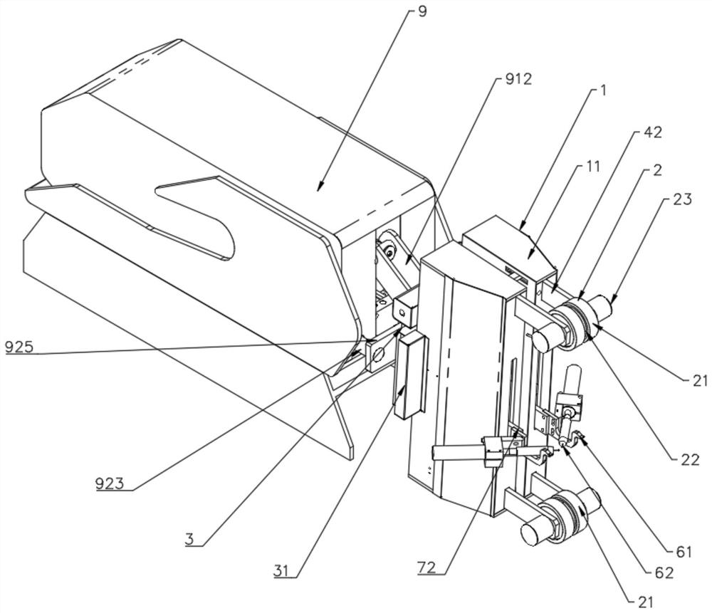
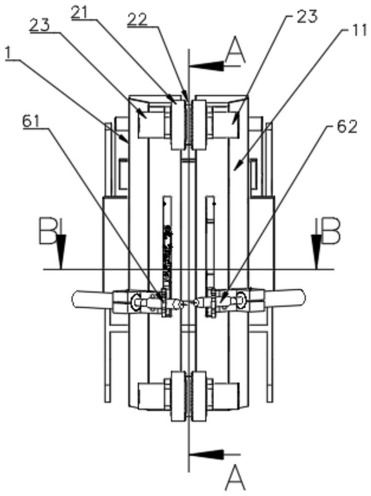
[0058] The adjustment mechanism 3 also includes a tension spring (not shown in the figure) arranged between the two mechanical arms 1 , and the direction of the tension spring is parallel to the sliding direction of the mechanical arm 1 relative to the connecting block 31 . In actual use, when the notch 22 in the tracking wheel body 21 is aligned and in contact with the rib, a forward thrust is applied to the mechanical arm 1. At this time, the tracking wheel body 21 will be subjected to a force pointing to both sides along its own axial direction. The component force of the tension spring 35 is extended by stretching (generating a restoring force in the opposite direction), and at this time, the two mechanical arms 1 will slide against each other relative to the connecting block 31, thereby realizing the adjustment of the width of the notch 22, that is, The width of the notch 22 varies freely with the diameter of the winding rib.

[0059] Further, the opening of the tracking ...

Embodiment 2

[0061] Such as Figure 6 As shown, the backs of the two mechanical arms 1 are respectively provided with nut seats 36 and through-hole seats 37 correspondingly. The through-hole seats 37 are perforated with a screw member 382 threadedly connected to the nut seats 36, and the two sides of the through-hole seats 37 are respectively pressed. Resists the first compression spring 35 sleeved on the screw member 382, ​​and the end of the screw member 382 away from the nut seat 36 and the through hole seat 37 is fixed with a pressing plate 381 pressed against the first compression spring 35 on the right side; further Yes, one end of the screw corresponding to the pressure plate 381 is formed with a manual adjustment hole (not marked in the figure). The interaction force of the two first compression springs 35 realizes the adjustment of the distance between the mechanical arms 1 .

Embodiment 3

[0063] Such as Figure 7 As shown, the adjustment mechanism 3 also includes a first screw rod 32 and a first connecting seat 33, and a first connecting seat 33 is respectively installed on the two mechanical arms 1, and the two first connecting seats 33 are threadedly connected to the first connecting seat 33 respectively. The two ends of the screw 32, the helical directions of the threads at the two ends of the first screw 32 are opposite.

[0064] Further, the adjustment mechanism 3 also includes a first drive motor 34, the first drive motor 34 is installed on one of the mechanical arms 1, and the output shaft of the first drive motor 34 is connected to the first screw rod 32 for driving the first screw rod 32 circular rotation. In this embodiment, the end of the first screw 32 away from the first driving motor 34 is formed with a manual adjustment slot 321 , which can be manually adjusted with tools such as a wrench.

[0065] Such as Figure 4 and Figure 9 As shown, th...


PUM


Abstract

The invention discloses a welding head of a self-adaptive reinforcement cage and a welding device of the self-adaptive reinforcement cage. The welding head comprises a mechanical arm and a tracking wheel set, the tracking wheel set is installed at the front end of the mechanical arm, the tracking wheel set comprises two tracking wheel bodies which are oppositely arranged, a notch is formed between the two tracking wheel bodies and used for pressing and abutting against a winding rib on the reinforcement cage to be welded, and the width of the notch can be adjusted. According to the welding head, the notch with the adjustable width is formed, so that the welding head can adapt to the outer diameter sizes of different single-winding ribs or double-winding ribs, the tracking wheel set does not need to be replaced when the winding ribs of different sizes are tracked, the production efficiency is improved, and meanwhile better practicability and adaptability are achieved.

Description

technical field [0001] The invention relates to the field of reinforcement cage welding, in particular to an adaptive reinforcement cage welding head and a welding device thereof. Background technique [0002] In the prior art, the invention patent with the application number 201810246300.6 discloses "a steel cage welding head and a steel cage welding device based on the head"; wherein: the steel cage welding head includes a shell, a welding torch chuck, and It includes a first mounting plate protruding from the inside of the shell to the front of the shell, the welding torch chuck is fixed on the front end of the first mounting plate, and a first driving device is arranged inside the shell, and the first driving device is used to drive the first mounting plate along the front of the shell. The body moves forward and backward; the first mounting plate can also move up and down in the housing; it also includes a wire tracking device fixedly installed on the front of the housi...

Claims


Application Information

Patent Timeline
IPC IPC(8): B23K37/00B23K37/02
CPCB23K37/00B23K37/02B23K37/0247B23K2101/22
Inventor 向光明
Owner 极智汇创智能科技(成都)有限公司
Why Eureka
Try Eureka