Tubular heat exchanger manufacturing and processing technology

A tubular heat exchanger and processing technology, applied in the field of heat exchanger manufacturing, can solve the problems of worker's personal safety, low installation efficiency, inconvenient placement and removal of tube sheets and heat exchange tubes, etc., to avoid direct Contact, pick and place convenient and quick effect

Active Publication Date: 2021-06-25
XIAN JUYUAN INFORMATION TECH CO LTD
View PDF9 Cites 1 Cited by
  • Summary
  • Abstract
  • Description
  • Claims
  • Application Information

AI Technical Summary

Problems solved by technology

[0004] 1. In the existing assembly of the tube sheet and the heat exchange tube, since the heat exchange tube is a U-shaped structure, the heat exchange tubes are installed manually on the tube sheet one by one according to the specifications from small to large, and the manual The installation efficiency of the heat exchange tube is low, which affects the production efficiency of the heat exchanger, and the manual assembly of the tube sheet and the heat exchange tube is easy to cause indentations or creases on the surface of the heat exchange tube, resulting in a decrease in the use value of the heat exchange tube, which affects the heat exchange. the quality of the device;
[0005] 2. In the existing assembly of tube sheets and heat exchange tubes, although the fixation of the tube sheets is firm, it is not very convenient to place and remove the tube sheets and heat exchange tubes before and after assembly, and manual control of the clamping equipment is required It not only affects the assembly efficiency of tube sheets and heat exchange tubes, but also brings certain personal safety problems to workers.

Method used


Image

  • Tubular heat exchanger manufacturing and processing technology
  • Tubular heat exchanger manufacturing and processing technology
  • Tubular heat exchanger manufacturing and processing technology

Examples


Embodiment Construction

[0032] In order to make the technical means realized by the present invention, creative features, goals and effects easy to understand, the following combination Figure 1 to Figure 6 , to further elaborate the present invention.

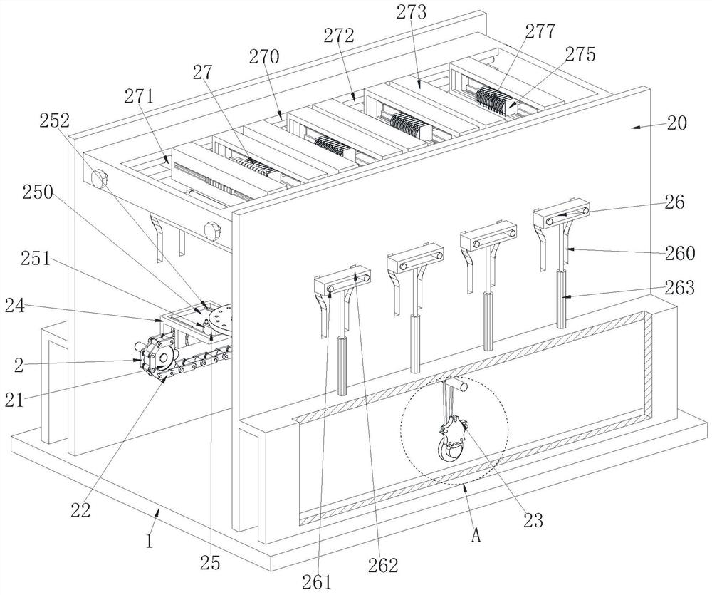
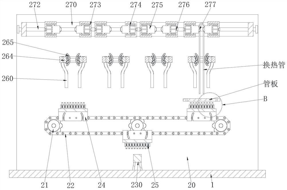
[0033] A tubular heat exchanger manufacturing and processing process, which uses a tubular heat exchanger manufacturing and processing equipment, the tubular heat exchanger manufacturing and processing equipment includes a base 1 and an assembly device 2, and adopts the above-mentioned tubular heat exchanger to manufacture The specific method for processing equipment to assemble the tube sheet and heat exchange tubes in the U-shaped tube heat exchanger is as follows:

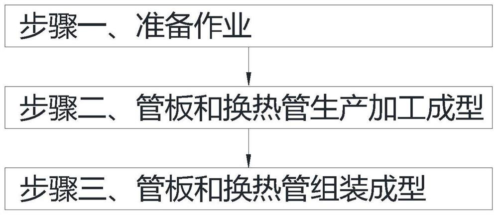
[0034] Step 1. Preparatory work: debug the manufacturing and processing equipment of the tubular heat exchanger;

[0035] Step 2: Production, processing and molding of tube sheets and heat exchange tubes: use existing production equipment to produce tube sheets and heat exchange tube...


PUM


Abstract

The invention relates to a tubular heat exchanger manufacturing and processing technology. The technology uses tubular heat exchanger manufacturing and processing equipment, the tubular heat exchanger manufacturing and processing equipment comprises a base and an assembling device, and the assembling device is arranged on the upper surface of the base. The equipment can solve the current problems that heat exchange tubes are of U-shaped structures, so that the heat exchange tubes are manually mounted on a tube plate one by one according to specifications from small to large, the manual mounting efficiency is lower, the production efficiency of the heat exchanger is influenced, moreover, indentations or creases are easy to appear on the surfaces of the heat exchange tubes when the tube plate and the heat exchange tubes are manually assembled, so that the use value of the heat exchange tubes is reduced, the quality of the heat exchanger is influenced, although the tube plate is firmly fixed, the tube plate and the heat exchange tubes are not very convenient to place and take down before and after being assembled, opening and closing of clamping equipment need to be manually controlled, the assembling efficiency of the tube plate and the heat exchange tubes is affected, and certain personal safety is brought to workers.

Description

technical field [0001] The invention relates to the field of heat exchanger manufacturing, in particular to a manufacturing process of a tubular heat exchanger. Background technique [0002] The tubular heat exchanger is composed of a shell, a heat transfer tube bundle, a tube sheet, a baffle (baffle) and a tube box. The shell is mostly cylindrical, and the tube bundle is installed inside. Above, there are two kinds of hot and cold fluids for heat exchange, one flows in the tube, called tube-side fluid; the other flows outside the tube, called shell-side fluid; U-tube heat exchanger is tube-type heat exchange It is a kind of heat exchanger, which is composed of main parts such as tube box, shell and tube bundle. On the tube plate, the characteristic is that the tube bundle can expand and contract freely, no thermal stress will be generated due to the temperature difference between the tube shells, and the thermal compensation performance is good; the tube pass is double tub...

Claims


Application Information

Patent Timeline
Patent Type & Authority Applications(China)
IPC IPC(8): B23P15/26
CPCB23P15/26
Inventor 王梦如
Owner XIAN JUYUAN INFORMATION TECH CO LTD
Why Eureka
Try Eureka