
Tube type heat exchanger forming assembly method

A technology of tube-and-tube heat exchanger and assembly method, which is applied in the field of heat exchanger manufacturing, and can solve the problem of misalignment of heat exchange tube holes, reduced assembly efficiency of tube sheets, heat exchange tubes and baffles, and time-consuming and laborious problems And other issues

Active Publication Date: 2021-07-06
江苏东南环保科技有限公司
View PDF10 Cites 1 Cited by
  • Summary
  • Abstract
  • Description
  • Claims
  • Application Information

AI Technical Summary

Problems solved by technology

[0004] 1. When the existing assembly of tube sheets, heat exchange tubes and baffles, due to the different shapes of the tube sheets and baffles, the existing clamping equipment for the tube sheets and baffles The clamping and fixing method is the same, resulting in the tube sheet can be clamped and fixed, but the baffle is difficult to be completely clamped and fixed, so that when the heat exchange tube is inserted into the hole on the tube sheet and the baffle When the baffle plate is unstable, the problem of instability of the baffle plate is likely to occur, which reduces the assembly efficiency of the tube sheet, heat exchange tubes and baffle plate;
[0005] 2. In the existing assembly of tube sheets, heat exchange tubes, and baffles, the clamping and fixing of the tube sheets and baffles is completely fixed after one-time position calibration. For subsequent assembly of heat exchange tubes, The problem of inaccurate hole alignment requires re-opening the clamping equipment to adjust the positions of the tube sheets and baffles, which is time-consuming and laborious, and seriously affects the production efficiency of the heat exchanger

Method used


Image

  • Tube type heat exchanger forming assembly method
  • Tube type heat exchanger forming assembly method
  • Tube type heat exchanger forming assembly method

Examples


Embodiment Construction

[0035] In order to make the technical means realized by the present invention, creative features, goals and effects easy to understand, the following combination Figure 1 to Figure 8 , to further elaborate the present invention.

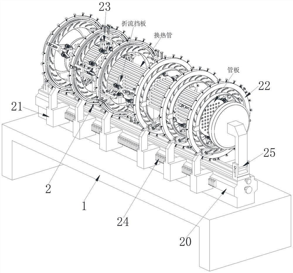
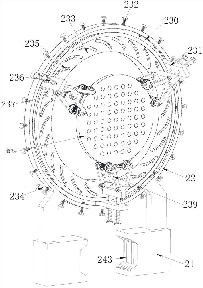
[0036]A method for forming and assembling a tube-and-tube heat exchanger, which uses a forming and assembling equipment for a tube-and-tube heat exchanger. The forming and assembling equipment for a tube-and-tube heat exchanger includes a base 1 and an auxiliary device 2. The heat exchanger forming and assembly equipment assembles the formed tube sheet, heat exchange tube and baffle plate of the tube-and-tube heat exchanger as follows:

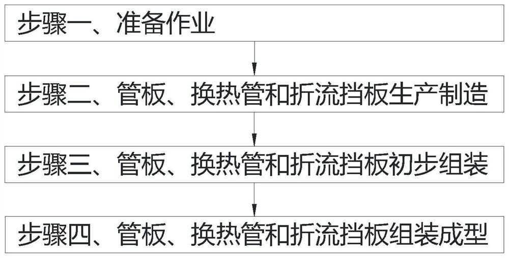
[0037] Step 1. Preparatory work: debug the forming and assembling equipment of the tube-and-tube heat exchanger;

[0038] Step 2. Manufacture of tube sheets, heat exchange tubes and baffles: use existing production equipment to produce the tube sheets, heat exchange tubes and baffles of the tube-and-tube heat excha...


PUM


Abstract

The invention relates to a tube type heat exchanger forming assembly method which uses tube type heat exchanger forming assembly equipment. The tube type heat exchanger forming assembly equipment comprises a base and an auxiliary device which is arranged on the upper surface of the base. The tube type heat exchanger forming assembly method can solve the current problems that as the shapes of a tube plate and a deflection baffle are different, but existing clamping equipment has the same clamping and fixing mode on the tube plate and the deflection baffle, it is difficult to completely clamp and fix the deflection baffle at the position where the tube plate can be clamped and fixed, the tube plate and the deflection baffle are completely fixed after one-time position calibration is performed for clamping and fixing, it is needed to open the clamping equipment again to adjust the positions of the tube plate and the deflection baffle for the problem of hole misalignment in subsequent assembly of heat exchange tubes, time and labor are wasted, and the heat exchanger production efficiency is seriously affected.

Description

technical field [0001] The invention relates to the field of heat exchanger manufacturing, in particular to a method for forming and assembling a tube-and-tube heat exchanger. Background technique [0002] Tube and tube heat exchanger is currently the most widely used heat exchanger in chemical industry and alcohol production. It is mainly composed of shell, tube sheet, heat exchange tube, head, baffle, etc. They are made of ordinary carbon steel, red copper, or stainless steel respectively. The structure of the shell and tube heat exchanger is relatively simple, compact and cheap. The outlet pipe at the other end of the head flows out, which is called the tube side; another fluid enters from the connecting pipe of the shell and flows out from the other connecting pipe on the shell, which is called the shell pass; [0003] At present, there are the following problems when assembling the formed tube sheets, heat exchange tubes and baffles of the tube-and-tube heat exchanger:...

Claims


Application Information

Patent Timeline
IPC IPC(8): B25B27/00B25B11/02
CPCB25B27/00B25B11/02
Inventor 林法翠
Owner 江苏东南环保科技有限公司
Learn More