Head mechanism of nondestructive hydraulic pipe dismounting device

A hydraulic pipe and hydraulic technology, applied in the direction of hand-held tools, manufacturing tools, etc., can solve the problem of uneven radial stress of pipe fittings, and achieve the effect of easy control of precision

Pending Publication Date: 2021-06-25
秦钱军
View PDF0 Cites 0 Cited by
  • Summary
  • Abstract
  • Description
  • Claims
  • Application Information

AI Technical Summary

Problems solved by technology

[0003] Existing pipe dismantling machines generally use single-cylinder hydraulic pressure, and the pipe fittings are roughly clamped by the chuck. Even if the pipe fittings can be removed, it is easy to deform due to uneven radial stress on the pipe fittings, especially the pipe fittings that have been severely corroded at the threaded joints. Almost impossible to remove

Method used


Image

  • Head mechanism of nondestructive hydraulic pipe dismounting device
  • Head mechanism of nondestructive hydraulic pipe dismounting device
  • Head mechanism of nondestructive hydraulic pipe dismounting device

Examples


Embodiment Construction

[0025] The following will clearly and completely describe the technical solutions in the embodiments of the present invention with reference to the accompanying drawings in the embodiments of the present invention. Obviously, the described embodiments are only some, not all, embodiments of the present invention. Based on the embodiments of the present invention, all other embodiments obtained by persons of ordinary skill in the art without making creative efforts belong to the protection scope of the present invention.

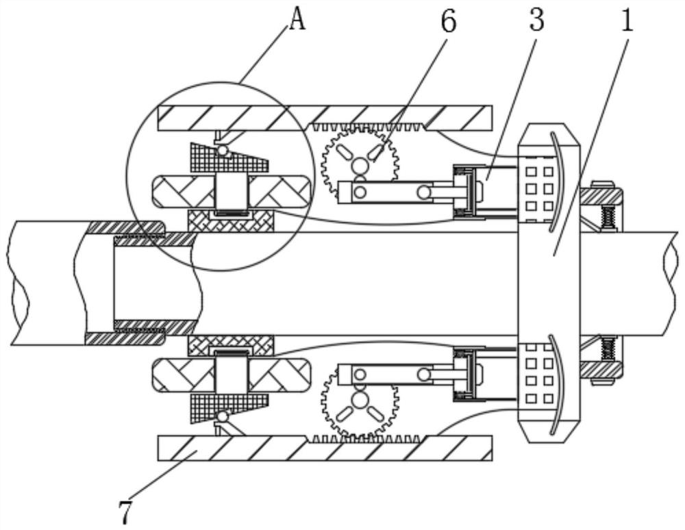
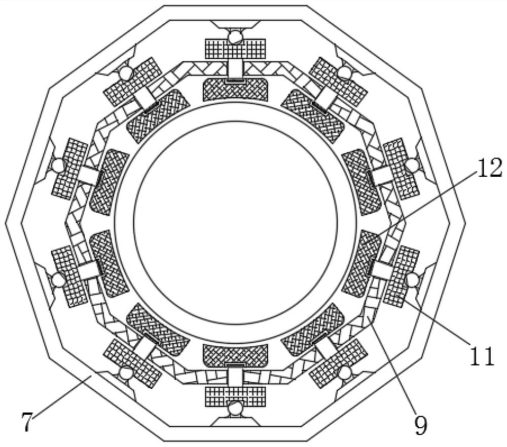
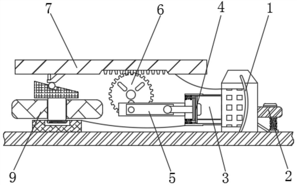
[0026] see Figure 1-5 , a head mechanism of a non-destructive hydraulic pipe dismantling device, including a driving end 1, an external pressure pipe 2 is arranged on the right side of the driving end 1, a number of hydraulic pipes 3 are arranged symmetrically on the left side of the driving end 1, and the left side of the hydraulic pipe 3 A hydraulic plug 4 is arranged inside the side, and the left end of the hydraulic plug 4 is interactively connected with ...


PUM


Abstract

The invention relates to the technical field of pipe dismounting machines, and discloses a head mechanism of a nondestructive hydraulic pipe dismounting device, which comprises a driving end, an external pressure pipe is arranged on the right side of the driving end, a plurality of hydraulic pipes are symmetrically arranged on the left side of the driving end, hydraulic plugs are arranged in the left sides of the hydraulic pipes, the left ends of the hydraulic plugs are interactively connected with push rods, middle wheels are arranged on the outer sides of the push rods, clamping sleeves are arranged on the outer sides of the middle wheels, pressure beads are arranged in the left sides of the clamping sleeves, and positioning sleeves are coaxially arranged in the clamping sleeves. According to the head mechanism of the nondestructive hydraulic pipe dismounting device, pressure beads move leftwards along inclined grooves in the upper surfaces of inclined surface blocks, so that the inclined surface blocks inwards push extrusion blocks to extrude pipes for necking down, gaps are formed in threaded connectors, meanwhile, inclined channels enable the inclined surface blocks to drive positioning sleeves to rotate, the threaded connectors rotate loosely, and micro rotation is added while necking down, so that the threaded connectors are loosened, and the pipes can be dismounted nondestructively.

Description

technical field [0001] The invention relates to the technical field of pipe dismantling machines, in particular to a head mechanism of a non-destructive hydraulic pipe dismantling device. Background technique [0002] The hydraulic pipe dismantling machine is a pipe dismantling equipment that has been put into use in response to the concept of energy saving and emission reduction in recent years. It mainly uses the strong pressure generated by the hydraulic cylinder to clamp the threaded metal pipe for non-destructive dismantling, so that the dismantled metal pipe can be retained as much as possible. Fully functional and ready for reuse. [0003] Existing pipe dismantling machines generally use single-cylinder hydraulic pressure, and the pipe fittings are roughly clamped by the chuck. Even if the pipe fittings can be removed, it is easy to deform due to uneven radial stress on the pipe fittings, especially the pipe fittings that have been severely corroded at the threaded jo...

Claims


Application Information

Patent Timeline
Patent Type & Authority Applications(China)
IPC IPC(8): B25B27/14
CPCB25B27/14
Inventor 秦钱军
Owner 秦钱军
Why Eureka
Try Eureka