Supercharge Your Innovation With Domain-Expert AI Agents!

Paper tube splitting machine convenient for arrangement after cutting

A paper tube slitting machine and post-finishing technology, which is applied in metal processing and other directions, can solve the problems of paper tubes that cannot be cut, paper tubes that cannot be sorted, and that fall to the ground.

Active Publication Date: 2021-06-25
吴江市恒达纸业有限公司
View PDF4 Cites 2 Cited by
  • Summary
  • Abstract
  • Description
  • Claims
  • Application Information

AI Technical Summary

Problems solved by technology

[0003] The existing technology is to manually place the paper tube to be cut on the cutting device, and then use the cutter to cut the paper tube, and the cut paper tube will be Falling to the ground, the paper tubes cannot be automatically cut evenly, and the cut paper tubes cannot be sorted

Method used


Image

  • Paper tube splitting machine convenient for arrangement after cutting
  • Paper tube splitting machine convenient for arrangement after cutting
  • Paper tube splitting machine convenient for arrangement after cutting

Examples


Embodiment 1

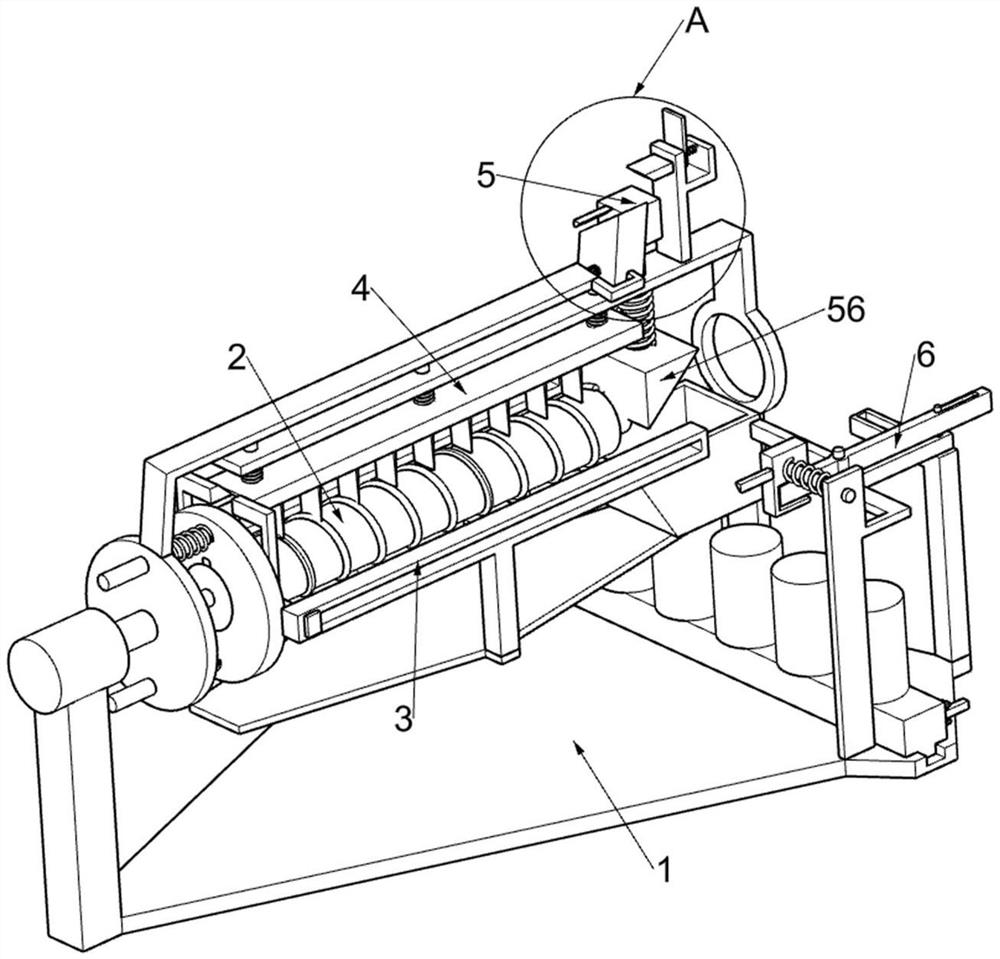
[0026] A paper tube slitting machine that is convenient for finishing after cutting, such as Figure 1-9 As shown, it includes a support frame 1, a rotating mechanism 2, a pushing mechanism 3 and a cutting mechanism 4. The supporting frame 1 is provided with a rotating mechanism 2, and the supporting frame 1 is provided with a pushing mechanism 3. The pushing mechanism 3 is used to push the nut 32 and The upper device moves away from the motor 21, and the pushing mechanism 3 is provided with a cutting mechanism 4, which is used for cutting the paper tube on the screw rod 26.

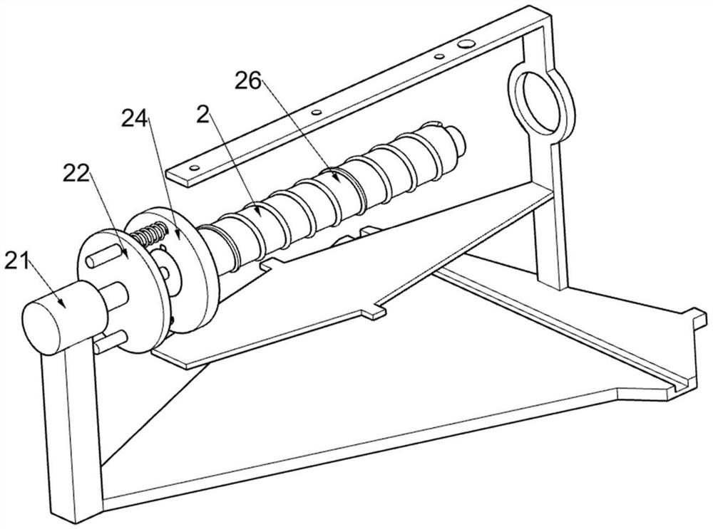
[0027] Turning mechanism 2 comprises motor 21, the first rotating disc 22, the first slide bar 23, the second rotating disc 24, the first back-moving spring 25 and screw rod 26, and bracing frame 1 is provided with motor 21, and motor 21 is used to drive the first A rotating disk 22 and its upper device are rotated, and one end of the output shaft of the motor 21 is provided with a first rotating disk 22...

Embodiment 2

[0033] On the basis of Example 1, such as Figure 7 As shown, it also includes a blocking mechanism 5, which is located on the rotating mechanism 2, and the blocking mechanism 5 includes a rotating frame 51, a first blocking frame 52, a first wedge block 53, a first torsion spring 54, a third slide Rod 55, second wedge block 56, third return spring 57, first fixed block 58, first wedge bar 59, second fixed frame 511, second sliding frame 512 and fourth return spring 513, first rotating disc 22 A turret 51 is provided on the turret 51, and a first stop frame 52 is provided on the turret 51. The first wedge block 53 is connected in rotation on the turret 51. The first wedge block 53 is used to push the first wedge bar 59 and its upper device. Moving upward, the first wedge block 53 is in contact with the first stop frame 52, and a first torsion spring 54 is connected between the first wedge block 53 and the turret 51, and the first torsion spring 54 is used to drive the first we...

Embodiment 3

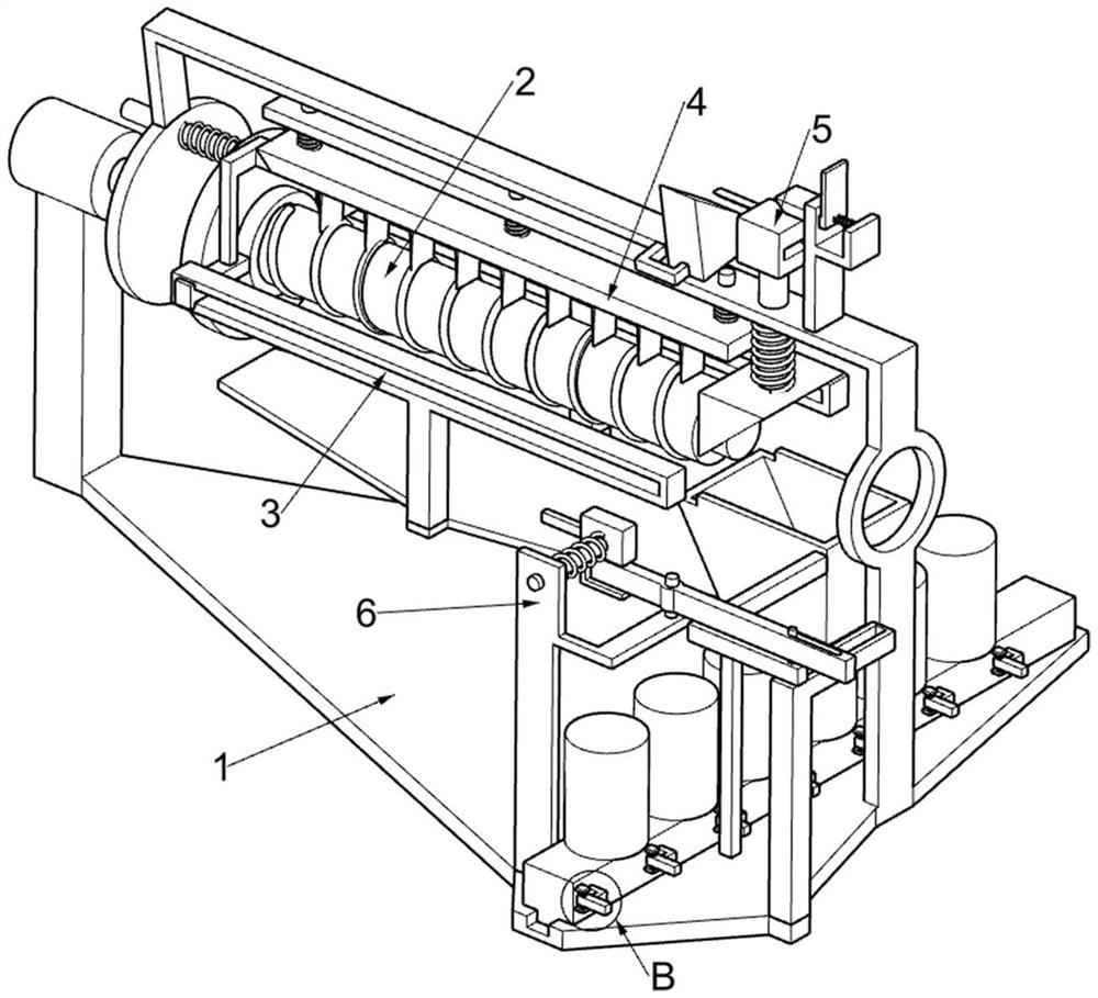
[0036] On the basis of Example 2, such as Figure 8-9 As shown, a finishing mechanism 6 is also included. The finishing mechanism 6 is arranged on the support frame 1. The finishing mechanism 6 is used to sort out the cut paper tubes. The finishing mechanism 6 includes a third fixed frame 61, a fourth slide bar 62, The second fixed block 63, the fifth return spring 64, the second wedge bar 65, the first fixed rod 66, the fourth fixed frame 67, the third sliding frame 68, the first rotating bar 69, the sliding frame 611, the sliding bar 612, The second fixed rod 613, the second rotating bar 614, the second stop frame 615 and the second torsion spring 616, the support frame 1 is provided with a third fixed frame 61, and the third fixed frame 61 is slidingly matched with a fourth slide bar 62, the fourth slide bar 62 is provided with a second fixed block 63, the fifth return spring 64 is connected between the second fixed block 63 and the third fixed frame 61, and the second fixe...


PUM


Abstract

The invention relates to a paper tube splitting machine, in particular to a paper tube splitting machine convenient for arrangement after cutting. The paper tube splitting machine comprises a supporting frame, a rotating mechanism, a pushing mechanism, a cutting mechanism and the like. The rotating mechanism is arranged on the supporting frame, the pushing mechanism is also arranged on the supporting frame, and the cutting mechanism is arranged on the pushing mechanism. Through an arrangement mechanism, a sliding frame pushes the slit paper tubes on the supporting frame to move in the direction away from a third fixing frame, so that the slit paper tubes on the supporting frame just fall off onto one second fixing rod, and a third sliding frame can push a second rotating strip to move by two units in the direction away from the third fixing frame. And preparation is made for the sliding frame to push the next slit paper tube onto the next second fixing rod, and the effect of automatically arranging the slit paper tubes is achieved.

Description

technical field [0001] The invention relates to a paper tube slitting machine, in particular to a paper tube slitting machine which is convenient for finishing after cutting. Background technique [0002] Paper tubes are widely used in chemical fiber industry, film industry, paper industry, metallurgical industry and other technical fields. They can be used as packaging tubes, medical equipment, calligraphy and painting, food cans, etc., and can also be used as paper tubes for temperature measurement and paper tubes for samplers. , battery paper tubes, paper tubes for fax machines, etc. When using paper tubes, it is necessary to cut the paper tubes. [0003] The existing technology is to manually place the paper tubes to be cut on the cutting equipment, and then use a cutter to cut the paper tubes. The cut paper tubes will fall to the ground, and the paper tubes cannot be cut evenly automatically. , It is impossible to organize the cut paper tubes. Contents of the inventi...

Claims


Application Information

Patent Timeline
Patent Type & Authority Applications(China)
IPC IPC(8): B26D3/16B26D7/04B26D7/18
CPCB26D3/16B26D7/01B26D7/04B26D7/1818B26D2007/013Y02P70/10
Inventor 袁玉志
Owner 吴江市恒达纸业有限公司
Features
  • R&D
  • Intellectual Property
  • Life Sciences
  • Materials
  • Tech Scout
  • Unparalleled Data Quality
  • Higher Quality Content
  • 60% Fewer Hallucinations
Learn More