Clamping device used based on movable contact group

A technology of moving contact and contact seat, which is applied to the locking mechanism for turnouts, electrical equipment for operating turnouts or circuit breakers, transportation and packaging, etc. problem, to achieve the effect of easy removal and installation, and quick fixation

Inactive Publication Date: 2021-06-25
西安晶海中德铁路电气有限公司
View PDF0 Cites 1 Cited by
  • Summary
  • Abstract
  • Description
  • Claims
  • Application Information

AI Technical Summary

Problems solved by technology

[0003] When fixing the moving contact seat and the moving contact column in the existing moving contact group, the fixing method is very complicated and takes a lot of time, and it is also very complicated to disassemble, which is very inconvenient to use

Method used


Image

  • Clamping device used based on movable contact group
  • Clamping device used based on movable contact group
  • Clamping device used based on movable contact group

Examples


Embodiment Construction

[0018] The present invention will be further described below in conjunction with the accompanying drawings and embodiments.

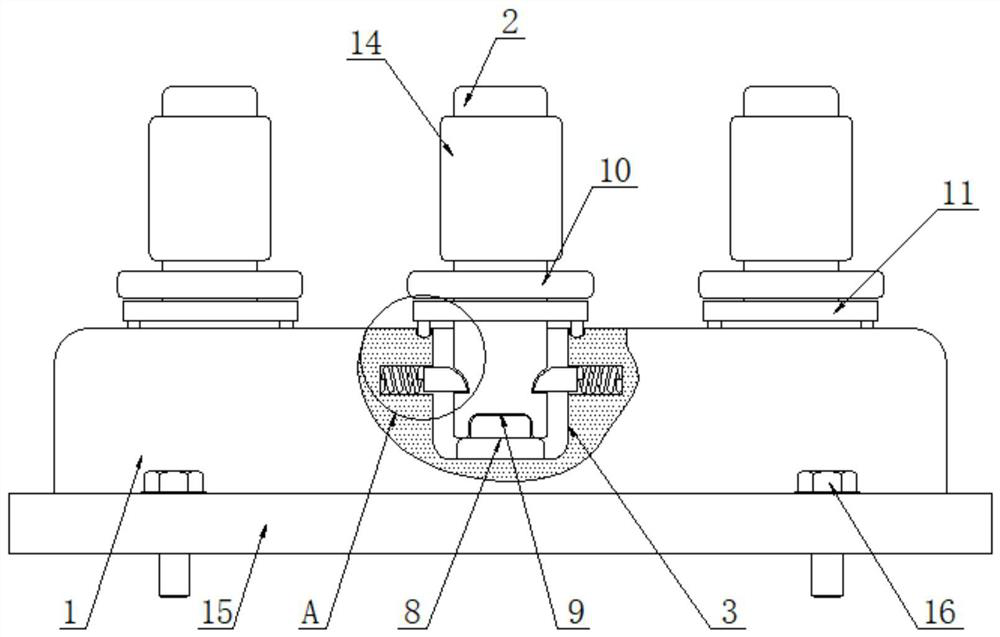
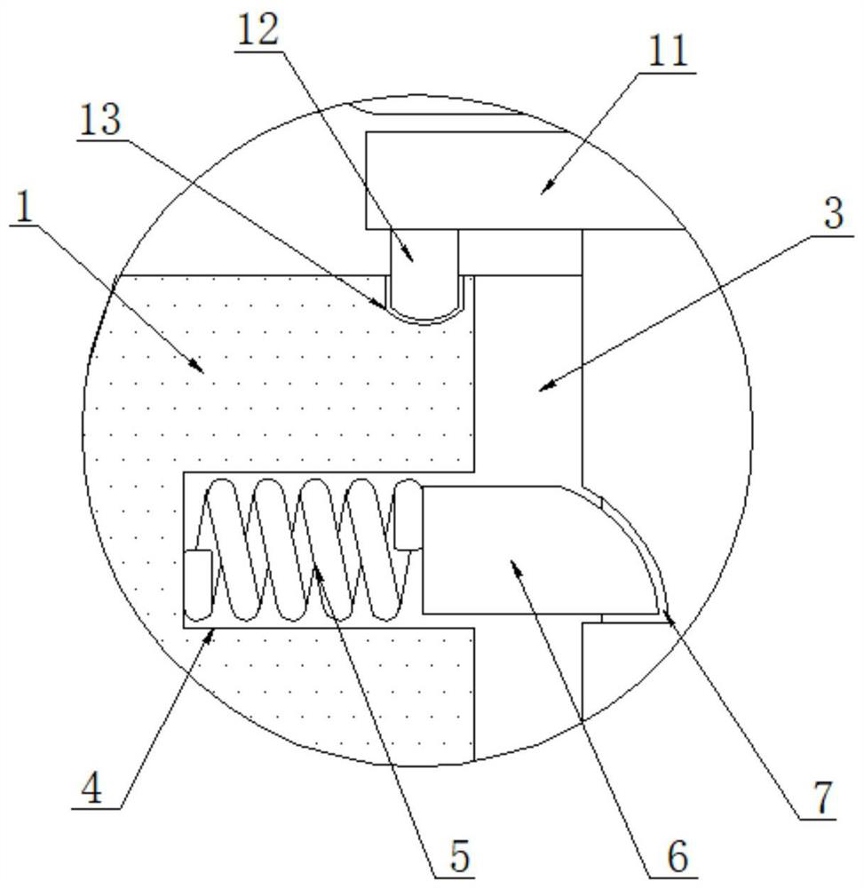
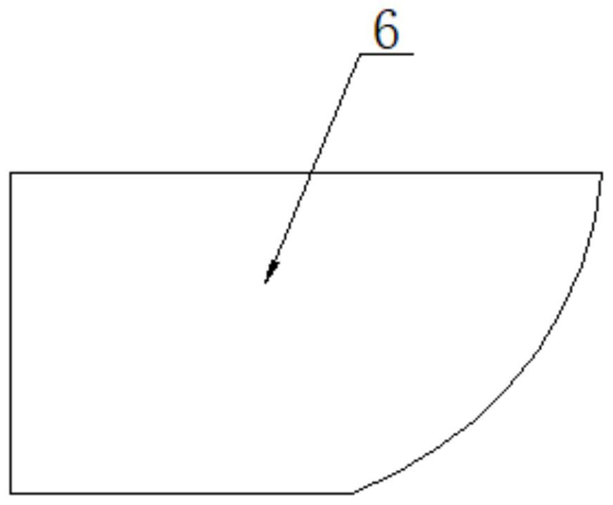
[0019] Please refer to figure 1 , figure 2 and image 3 ,in, figure 1 It is the front view of the structure of the present invention; figure 2 for the invention figure 1 Partial enlarged view of A in the center; image 3 It is a top view of the locking block structure of the present invention. The clamping device based on the moving contact group includes a moving contact seat 1, the surface of the moving contact seat 1 is fixedly connected to the limit plate 15, the top of the limit plate 15 is threaded with a fastening bolt 16, and the bottom end of the fastening bolt 16 Through the top of the limiting plate 15 and extending to the bottom of the limiting plate 15, the top of the moving contact seat 1 is movably connected with the moving contact post 2, and the surface of the moving contact post 2 above the threaded ring 10 is fixedly connected...


PUM


Abstract

The invention discloses a clamping device used based on a movable contact group. The clamping device comprises a movable contact seat, the top of the movable contact seat is movably connected with a movable contact column, the bottom end of the movable contact column penetrates through the top of the movable contact seat and extends to an inner cavity of the movable contact seat, the inner cavity of the movable contact seat is provided with an adaptive groove which is movably connected with the surface of the movable contact column, and an inner cavity of the adaptive groove is provided with a spring groove. The invention relates to the technical field of movable contact groups. According to the clamping device used based on the movable contact group, a movable contact column is inserted into an adaptive groove, a connecting groove in the bottom is adaptive to a connecting column, clamping is completed, at the moment, a clamping block abuts against the surface of the movable contact column, a top spring is compressed to retract into a spring groove, then the movable contact column is rotated, and the surface of the clamping block makes contact with the surface of a clamping groove; and pushed by a top spring, the clamping block is clamped in the clamping groove to fix the connecting column, so that the connecting column can be quickly fixed, and the connecting column is very convenient to take out and mount.

Description

technical field [0001] The invention relates to the technical field of moving contact groups, in particular to a clamping device based on moving contact groups. Background technique [0002] The dynamic and static contact groups are used to control the position of the switch and realize the electrical interlocking of the railway point machine. The dynamic and static contact groups are extremely important signal components. The moving contact group, the static contact fixedly installed on the contact seat, and the dust-proof arc extinguishing cover covering the dynamic and static contact, when the switch is switched, the moving contact bracket in the switch machine will drive the moving contact group to contact with the static contact assembly, To further realize the signal transmission of electrical equipment, at present, the existing moving contact group includes a column made of phenolic glass fiber with three power supply rings installed, and the moving contact ring is in...

Claims


Application Information

Patent Timeline
Patent Type & Authority Applications(China)
IPC IPC(8): B61L5/06B61L5/10
CPCB61L5/06B61L5/102
Inventor 王刚张黎王强
Owner 西安晶海中德铁路电气有限公司
Why Eureka
Try Eureka