
A Joint Adjustment Method of Nozzle and Test Section in Plane Cascade Subsonic Test Device

A test device and test section technology, applied in the field of aero-engine basic research and test equipment, can solve the problems of no nozzle outlet height adjustment, high labor intensity, sudden change in nozzle outlet size, etc., so as to save the test preparation time and improve the test Efficiency, the effect of reducing labor intensity

Active Publication Date: 2022-04-19
中国空气动力研究与发展中心空天技术研究所
View PDF0 Cites 0 Cited by
  • Summary
  • Abstract
  • Description
  • Claims
  • Application Information

AI Technical Summary

Problems solved by technology

The existing planar subsonic cascade test device, because most of the sonic nozzles are solid nozzles, does not have the function of adjusting the height of the nozzle outlet. The outlet is connected to transition sections of different heights and replaced with different lengths of the upper and lower walls of the test section. This method of adjusting the height of the nozzle and the upper and lower walls of the test section brings many disadvantages: 1. The connection between the transition sections of different heights and the nozzle will cause nozzle Sudden changes in outlet size and steps lead to poor flow field quality in the test section and reduced test accuracy; 2. When changing the test state, it is necessary to frequently replace the upper and lower wall panels of different height transition sections and different lengths of the test section, which is extremely inconvenient to operate and labor-intensive. The strength is high and the test efficiency is low; 3. The continuous adjustment of the height of the nozzle and the height of the test section cannot be realized, and the continuous adjustment of the length of the upper and lower wall panels of the test section cannot be realized, which may cause some test conditions to be unrealized

Method used


Image

  • A Joint Adjustment Method of Nozzle and Test Section in Plane Cascade Subsonic Test Device
  • A Joint Adjustment Method of Nozzle and Test Section in Plane Cascade Subsonic Test Device
  • A Joint Adjustment Method of Nozzle and Test Section in Plane Cascade Subsonic Test Device

Examples


Embodiment 1

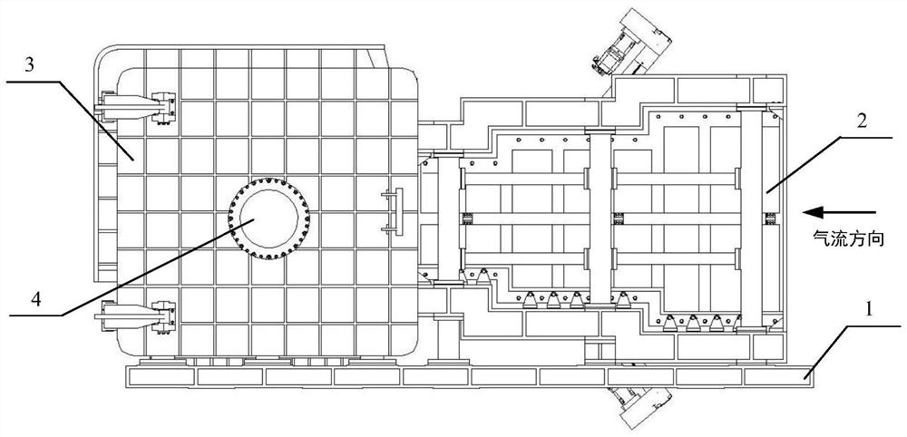
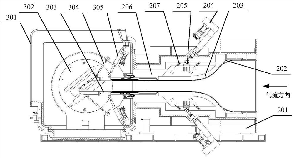
[0061] In the planar cascade subsonic test device of this embodiment, the joint adjustment method of the nozzle and the test section is used. The height-adjustable sonic nozzle 2 of the planar cascade subsonic test device used in the joint adjustment method is 1340 mm high × 190 mm wide. , Adjustable height The outlet height of the sonic nozzle 2 can be adjusted from 235mm to 445mm; the angle of the upper and lower panels can be adjusted from -5° to 5°, and the length of the upper and lower panels can be adjusted from 0 to 400mm.

[0062] The flow field calibration test shows that the deviation of the core area of ​​the flow field in the test section of the subsonic test chamber 3 is better than 0.003 when the Mach number is 0.8, which has reached the advanced level of GJB 1179A-2012 in the "Quality Requirements for Flow Fields of Low-speed Wind Tunnels and High-speed Wind Tunnels". index.


PUM


Abstract

The invention discloses a method for joint adjustment of a spray pipe and a test section in a subsonic speed test device of a plane cascade. In this joint adjustment method, the joint adjustment of the height of the nozzle outlet and the height of the upper and lower walls of the test section is realized through the height regulator in the height-adjustable sonic nozzle and the wall panel angle regulator of the subsonic test cabin; Wallboard length adjuster, to realize the length adjustment of the upper and lower wallboards in the test section. This joint debugging method can conveniently and quickly realize the combined adjustment of the outlet height of the subsonic nozzle and the height and length of the upper and lower wall panels of the test section, which meets the requirements of various types of planar cascade subsonic aerodynamic performance test research and technical verification, and saves test preparation. Time, improve the test efficiency.

Description

technical field [0001] The invention belongs to the field of test equipment for basic research of aero-engines, and in particular relates to a method for joint adjustment of a nozzle and a test section in a plane cascade subsonic test device. Background technique [0002] Aviation turbines (including fans / compressors and turbines) and gas turbines are key components for maintaining thermal cycles and generating thrust, and the aerodynamic shape of their rotor / stator blades determines the aerodynamic performance of aviation turbines and gas turbines. In order to design high-performance aerojet engines and gas turbines, it is necessary to study the design method and flow characteristics of the turbine at the cascade (two-dimensional airfoil) level. In order to conduct experimental research on cascade channel flow under real flight conditions on the ground, it is necessary to build ground equipment that can simulate parameters such as the Mach number and Reynolds number of the ...

Claims


Application Information

Patent Timeline
Patent Type & Authority Patents(China)
IPC IPC(8): G01M15/02G01M15/14
CPCG01M15/02G01M15/14
Inventor 魏巍时培杰任思源马护生李学臣陈峰黄康宗有海江辉谭锡容叶敏李聪
Owner 中国空气动力研究与发展中心空天技术研究所
Learn More