Double-nozzle type giant magnetostrictive jet servo valve and working method

A technology of giant magnetostrictive and giant magnetostrictive rods, which is applied in the direction of servo motor components, fluid pressure actuators, mechanical equipment, etc., can solve the problems of energy loss, servo valve performance degradation, large volume, etc., to reduce thermal expansion Combined with heat-induced displacement, improved output displacement accuracy, and high displacement output accuracy

Inactive Publication Date: 2014-01-29
NANJING UNIV OF AERONAUTICS & ASTRONAUTICS
View PDF7 Cites 0 Cited by
  • Summary
  • Abstract
  • Description
  • Claims
  • Application Information

AI Technical Summary

Problems solved by technology

[0004] There are several defects in this kind of giant magnetostrictive electro-mechanical converter: it is driven by two giant magnetostrictive electro-mechanical converters, which increases the complexity of the structure and drive; it is necessary to ensure that the two giant magnetostrictive rods When the temperature is equal, the thermal expansion can be equal, so as to ensure that the servo valve is less affected by the temperature; the bias magnetic field is generated by the energized coil, because the bias magnetic field strength is required to be constant when the servo valve is working and the bias magnetic field strength is relatively large, so the bias The coil heats up seriously, and the cooling system is not designed, which not only causes energy loss, but also reduces the performance of the servo valve
[0012] To sum up, among the existing giant magnetostrictive electro-mechanical converter drive methods for electro-hydraulic servo valves, although the double-coil drive has the advantages of convenient adjustment of the drive magnetic field, it has the disadvantages of large volume, severe heat generation, and low GMA output accuracy. Disadvantages: Although the permanent magnet single-coil drive has the advantages of low heat generation, compact structure, and small volume, it is inconvenient to adjust the driving magnetic field, especially the demagnetization phenomenon caused by the magnetic drop of the permanent magnet cannot be adjusted in time to affect the GMA control accuracy.

Method used


Image

  • Double-nozzle type giant magnetostrictive jet servo valve and working method
  • Double-nozzle type giant magnetostrictive jet servo valve and working method
  • Double-nozzle type giant magnetostrictive jet servo valve and working method

Examples


Embodiment Construction

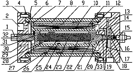
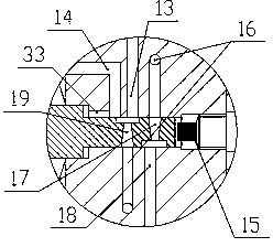
[0054] Such as figure 1 , shown in 2 and 3, a dual-nozzle type giant magnetostrictive jet servo valve, comprising a giant magnetostrictive electric-machine converter and a jet amplifier, is characterized in that:

[0055] The above-mentioned giant magnetostrictive electro-mechanical converter includes an outer cover 4, a left end cover 3 and a right end cover 20 installed at two ends of the outer cover, a bobbin 7 installed in the outer cover, one end of the bobbin 7 is fixed with the right end cover 20, and the other end is connected with the left end cover. There is a gap in the cover 3; a bias magnetic field generating unit and a driving magnetic field generating unit are installed on the coil bobbin 7;

[0056] It also includes a giant magnetostrictive rod 24 installed in the coil frame 7. The side of the giant magnetostrictive rod 24 close to the left end cover is a magnetic fixed end, and the fixed end of the magnetostrictive rod is equipped with a slider 31, which is c...


PUM


Abstract

The invention discloses a double-nozzle type giant magnetostrictive jet servo valve and a working method, belonging to the technical field of hydraulic servo control. The valve comprises a left end cover (3), a right end cover (20), a giant magnetostrictive rod (24), a coil framework (7), a bias magnetic field generation unit, a driving magnetic field generation unit, an output rod (22) and a pre-pressed spring (21). The output rod (22) and the right end cover (20) form a jet hydraulic amplifier. According to the novel jet servo valve, double nozzles and double receivers are distributed independently; the tangent configuration or the cross configuration of the double receivers, which cannot be realized by a single-nozzle double-receiver jet servo valve, can be realized; meanwhile, the jet servo valve is driven by a novel giant magnetostrictive actuator, so that the jet servo valve has the advantages of being rapid in response, high in pressure sensitivity and the like; meanwhile, a driving part of the jet servo valve is driven by double permanent magnetic coils, so that the jet servo valve has the obvious characteristics of lower heating influence, adjustable bias magnetic field, finely adjustable zero position of the servo valve and the like.

Description

technical field [0001] The invention relates to the application of giant magnetostrictive materials and belongs to the technical field of hydraulic servo control. Background technique [0002] The traditional structure of the jet servo valve is generally composed of a torque motor, a jet tube, a nozzle, a double receiver, etc. The torque motor is used to drive the deflection of the jet tube, and the deflection of the jet tube can change the pressure and flow in the double receiver. The change can be used to drive the spool valve or the hydraulic actuator in the small and medium power hydraulic servo system, and the control of the spool valve or the hydraulic actuator can be realized by controlling the output force and displacement of the torque motor. [0003] Document 1 (two-phase opposed giant magnetostrictive self-sensing force feedback two-stage servo valve and control method, Wang Xinhua, national invention patent, patent application number: 200710178688.2) proposed a g...

Claims


Application Information

Patent Timeline
Patent Type & Authority Patents(China)
IPC IPC(8): F15B13/02
Inventor 朱玉川李跃松鲍和云成奇峰
Owner NANJING UNIV OF AERONAUTICS & ASTRONAUTICS
Why Eureka
Try Eureka