
Optical alignment device and optical alignment method

A technology of optical alignment and alignment, which is applied in optics, nonlinear optics, instruments, etc., and can solve problems such as increased difficulty of friction alignment process

Active Publication Date: 2021-12-31
HKC CORP LTD
View PDF8 Cites 0 Cited by
  • Summary
  • Abstract
  • Description
  • Claims
  • Application Information

AI Technical Summary

Problems solved by technology

However, the above is only applicable to the case where the alignment direction is uniform. When the liquid crystal molecules corresponding to several array substrates arranged on the large glass plate need different alignment directions, the difficulty of the rubbing alignment process will increase and will no longer be applicable.

Method used


Image

  • Optical alignment device and optical alignment method
  • Optical alignment device and optical alignment method
  • Optical alignment device and optical alignment method

Examples


Embodiment Construction

[0036]In order to make the purpose, technical solution and advantages of the present application clearer, the present application will be further described in detail below in conjunction with the accompanying drawings and embodiments. It should be understood that the specific embodiments described here are only used to explain the present application, and are not intended to limit the present application.

[0037] Unless otherwise defined, the technical terms or scientific terms used in this application shall have the usual meanings understood by those skilled in the art. The terms "first", "second", "third", "fourth" and similar words used in the specification and claims of this application do not indicate any order, quantity or importance, but are only used to distinguish different components. Thus, a feature defined as "first", "second", "third" and "fourth" may expressly or implicitly include one or more of such features. In the description of the embodiments of the pres...


PUM


Abstract

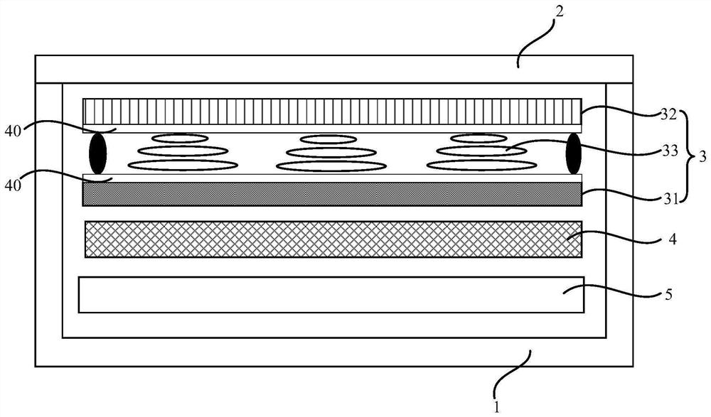
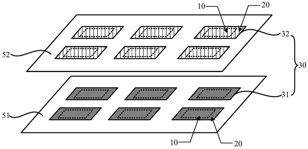
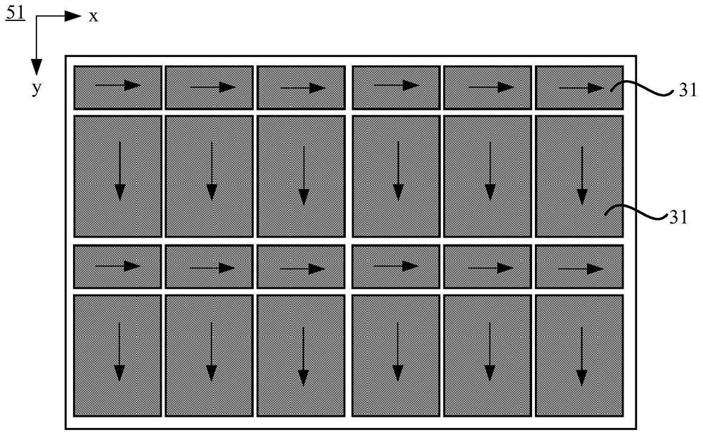
The application provides a light alignment device and a light alignment method, which relate to the field of display technology. The light alignment device includes: a carrying platform, a linearly polarized light source located on one side of the carrying platform, and a linearly polarized light source located between the carrying platform and the linearly polarized light source. The control component of the control component, the side of the carrier table close to the control component is used to place the large plate glass to be aligned including multiple alignment areas; the linearly polarized light source is used to provide the first polarized light to the control component; the control component is used to adjust the second The polarization direction of the first polarized light is provided, and the second polarized light is provided to a plurality of alignment regions included in the large plate glass to be aligned; wherein, the polarization directions of the second polarized light corresponding to at least two alignment regions are different. The optical alignment device of the present application can simultaneously align multiple array substrates or multiple color filter substrates that require different alignment directions of liquid crystals, and the process is simple and the time is short.

Description

technical field [0001] The present application belongs to the field of display technology, and in particular relates to an optical alignment device and an optical alignment method. Background technique [0002] Liquid crystal display panels (Liquid Crystal Display, LCD) have the advantages of low radiation, small size and low energy consumption, and are widely used in various electronic devices such as notebook computers and televisions. Among them, the liquid crystal display panel usually includes an array substrate (Thin Film Transistor, TFT), a color filter substrate (Color Filter, CF), a liquid crystal (Liquid Crystal, LC) sandwiched between the array substrate and the color filter substrate, and a sealant, etc. . [0003] During the preparation process, several array substrates arranged on the first large glass plate and several color filter substrates arranged on the second large glass plate are usually prepared first, and then the array substrates on the two large gl...

Claims


Application Information

Patent Timeline
Patent Type & Authority Patents(China)
IPC IPC(8): G02F1/1337G02F1/133
CPCG02F1/133788G02F1/133753G02F1/13306G02F1/0136G02F1/133331G02F1/13336G02F1/133617G02F1/13362G02F1/134309G02F1/137
Inventor 何静余思慧
Owner HKC CORP LTD
Learn More