Eureka AIR delivers breakthrough ideas for toughest innovation challenges, trusted by R&D personnel around the world.

Small component concrete vibrating device

A vibrating device and component technology, applied in ceramic molding machines, auxiliary molding equipment, manufacturing tools, etc., can solve the problems of small structure size, safety accidents, affecting the strength of concrete components, etc., to achieve easy manufacturing and replacement, and reduce engineering costs. Effect

Active Publication Date: 2021-06-29
中铁二十五局集团第三工程有限公司
View PDF8 Cites 0 Cited by
  • Summary
  • Abstract
  • Description
  • Claims
  • Application Information

AI Technical Summary

Problems solved by technology

[0002] During bridge or building construction, prefabricated concrete prefabricated slabs or some concrete components are usually required. In the manufacturing process of concrete components, the mold cavity of the concrete component needs to be made first, and then the concrete cavity is poured by a mixer truck. Due to the pouring process, The mold cavity is usually equipped with a pre-embedded steel structure support frame. Although the concrete is fluid, there will still be air in the concrete layer. If the air inside the concrete member is not eliminated, cavities or voids will be formed after the concrete solidifies, which will seriously Affect the strength of concrete components, reduce the quality of concrete components, and may cause safety accidents in severe cases
[0003] In the prior art, a vibrator is usually used to vibrate concrete components to discharge the air in the poured concrete components and further mix the concrete evenly. However, in the manufacturing process of some small components, due to the small component structure The size is small, and there is a pre-embedded steel frame in the mold cavity, so the front end of the vibrating rod cannot enter the concrete layer for vibration

Method used


Image

  • Small component concrete vibrating device
  • Small component concrete vibrating device
  • Small component concrete vibrating device

Examples


Embodiment Construction

[0054] Embodiments of the present invention are described in detail below, examples of which are shown in the drawings, wherein the same or similar reference numerals designate the same or similar elements or elements having the same or similar functions throughout. The embodiments described below by referring to the figures are exemplary only for explaining the present invention and should not be construed as limiting the present invention.

[0055] In describing the present invention, it should be understood that the terms "center", "longitudinal", "transverse", "length", "width", "thickness", "upper", "lower", "front", " Rear", "Left", "Right", "Vertical", "Horizontal", "Top", "Bottom", "Inner", "Outer", "Axial", "Radial", "Circumferential" The orientation or positional relationship indicated by etc. is based on the orientation or positional relationship shown in the drawings, and is only for the convenience of describing the present invention and simplifying the descriptio...


PUM


Abstract

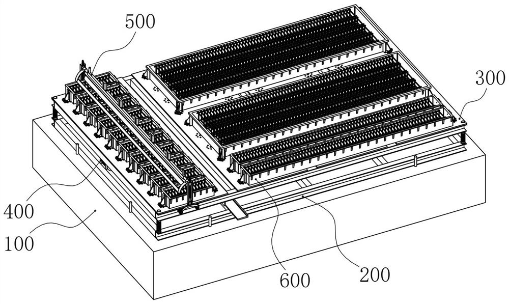
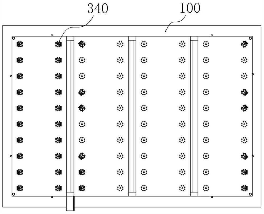
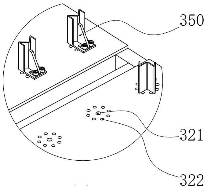
The invention discloses a small component concrete vibrating device. The small component concrete vibrating device comprises a base, a vibration platform, a vibration mechanism and compaction mechanisms; the vibration platform is installed above the base, an elastic supporting structure is arranged between the vibration platform and the base, a positioning assembly is arranged on the vibration platform, the positioning assembly is used for carrying out positioning on a concrete member mold; the vibration mechanism is installed on the vibration platform and located between the vibration platform and the base; and the compaction mechanisms are installed on the two sides of the vibration platform in a sliding mode, and the compaction mechanisms are used for carrying out compaction on concrete in the concrete member mold on the vibration platform. The compaction mechanisms are slidably installed on the two sides of the vibration platform and can conduct reciprocating motion on the vibration platform and carrying out compaction on the concrete in the concrete member mold on the vibration platform at the same time; and according to the small component concrete vibrating device, the vibration platform is arranged, the vibration platform can be used for placing concrete component molds of various sizes including small concrete components, and the applicability is extremely wide.

Description

technical field [0001] The invention relates to concrete construction equipment, in particular to a concrete vibrating device for small components. Background technique [0002] During bridge or building construction, prefabricated concrete prefabricated slabs or some concrete components are usually required. In the manufacturing process of concrete components, the mold cavity of the concrete component needs to be made first, and then the concrete cavity is poured by a mixer truck. Due to the pouring process, The mold cavity is usually equipped with a pre-embedded steel structure support frame. Although the concrete is fluid, there will still be air in the concrete layer. If the air inside the concrete member is not eliminated, cavities or voids will be formed after the concrete solidifies, which will seriously It affects the strength of concrete components, reduces the quality of concrete components, and may cause safety accidents in severe cases. [0003] In the prior art...

Claims


Application Information

Patent Timeline
IPC IPC(8): B28B1/087B28B17/00
CPCB28B1/0873B28B17/00
Inventor 谭剑曹智波申佩唐建武王革新谌荣华周烽杨磊黄敏黄晓帅刘志邓谦陈功彭向东
Owner 中铁二十五局集团第三工程有限公司
Why Eureka
Eureka Blog
Learn More