A method for removing an end piece and an apparatus for processing a substrate

A technology of edge material and substrate, applied in glass cutting devices, manufacturing tools, glass manufacturing equipment, etc., can solve problems such as poor yield, and achieve the effect of suppressing scars such as sheath tails or gaps

Inactive Publication Date: 2021-06-29
MITSUBOSHI DIAMOND IND CO LTD
View PDF0 Cites 0 Cited by
  • Summary
  • Abstract
  • Description
  • Claims
  • Application Information

AI Technical Summary

Problems solved by technology

At this time, if Figure 12 As shown, although the substrate M before the depression is formed is processed by the cutter wheel into the "U"-shaped scribing line S1 of the border line of the trim, and then the trim 22 is removed, but since the left and right sides of the trim 22 are parallel Therefore, only the edge material is grasped by a chuck and pulled away in the direction of separation, and the left and right sides of the edge material and the fracture surface of the product part 1 adjacent to it will rub against each other, resulting in a sheath tail or a gap, or an irregular shape in the product part. There is a problem of poor yield due to scratches such as cracks in the horizontal direction

Method used


Image

  • A method for removing an end piece and an apparatus for processing a substrate
  • A method for removing an end piece and an apparatus for processing a substrate
  • A method for removing an end piece and an apparatus for processing a substrate

Examples


no. 1 approach

[0041] Hereinafter, a first embodiment of the method of removing the method of the boundary portion of the present invention will be described in detail with reference to the drawings.

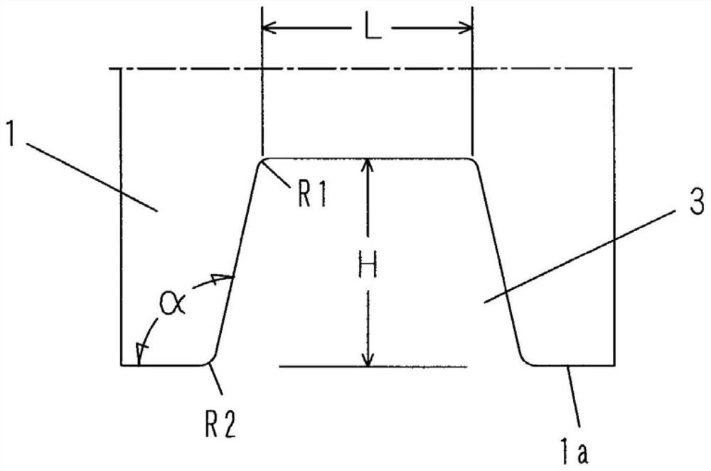
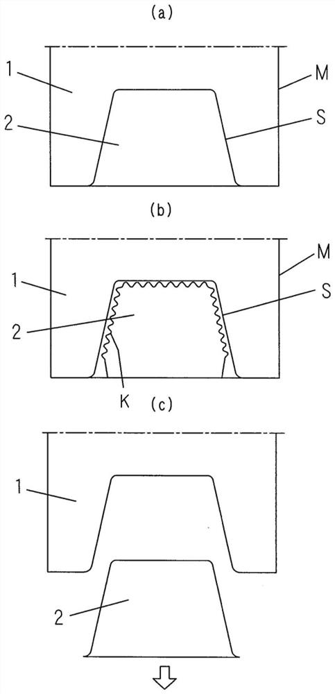
[0042] image 3 (A) shows the substrate M in which the front portion removes the front portion. The substrate M is a brittle material substrate such as glass, and has a product portion 1 and a binder portion 2 that distinguishes between the boundary scribing line S. The binder portion 2 is a trapezoidal shape of the rear portion to a narrower, and is formed on the edge 1a of the substrate M. figure 1 The product portion 1 removed after the binding portion 2 is shown, and the trapezoidal shape of the trapezoidal shape having a narrow width of the rear portion is formed by removing the edge portion 2. In the present embodiment, the length H of the trapezoidal shape is set to 50 mm, and the top length L is set to 50 mm, and the tilt angle α of the side is 102 °, so that the corner portion R1 and the ...

no. 2 approach

[0055] Hereinafter, a method of removing the boundary portion of the second embodiment of the present invention will be described in detail with reference to the accompanying drawings. In addition, the same components as those in the first embodiment are marked and the description thereof will be omitted.

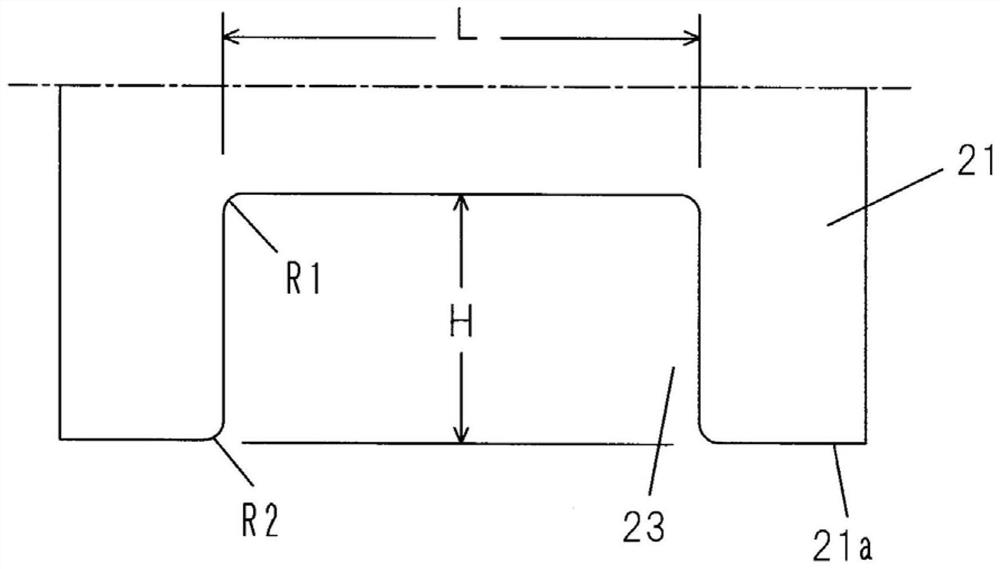
[0056] Figure 7 (A) shows the substrate M1 before the side material is removed. The substrate M1 is constituted by a brittle material substrate such as glass, and has a product portion 21 and a binder portion 22 divided by the boundary scribing line S1. The bound portion 22 is a "コ" shape of one end opening, and is formed on the edge 21a of the substrate M1. The left and right edges of the "コ" glyph are parallel. figure 2 The product portion 21 removing the binder portion 22 is shown to form a "コ" shaped recess 23 by removing the binder portion 22. In the present embodiment, the length H of the depressed portion 23 is set to 60 mm, and the bottom edge length L is set to 120 mm...


PUM


Abstract

The invention discloses a method for removing an end part and an apparatus for processing a substrate, which can inhibit the generation of scratches or defective products on a broken end surface. The method of the present invention is a method for removing, from a substrate (M), an edge part (2) recessed inward from the edge of the substrate, comprising: a first step for processing a boundary line (S) that forms a boundary line between a product section (1) and the edge part (2); a second step of allowing a pressing roller (4) having a flat circumferential surface to describe a trajectory (K) that repeatedly approaches and leaves a boundary lineation line (S) along the vicinity of the boundary lineation line (S) on the surface on the side of the rim section (2) while pressing to advance so that the boundary lineation line (S) is pre-broken or fragile; and a third step for removing the edge part (2) by pulling the edge part (2) in the direction away from the product part (1).

Description

Technical field [0001] The present invention relates to a method and a substrate processing apparatus for separating the concave formation of the concave-shaped edge portion from the substrate composed of a brittle material such as glass. Background technique [0002] In general, when cutting from a substrate that is a substrate which is a base material, it is necessary to separate unwanted binder portions (for example, refer to Patent Document 1). Typically, for the separation of the boundary portion, the row line of the substrate and the boundary portion of the border portion is processed in a cutting edge portion, and thereafter, the boundary portion is bent or drawn from the unit substrate. [0003] For unit substrates (hereinafter referred to as product portions), as described below figure 1 As shown, there is a structure in which a trapezoidal shape 3 having a rear portion is sequentially narrowed in the edge 1a of the product portion 1. At this time, most of them use Figur...

Claims


Application Information

Patent Timeline
Patent Type & Authority Applications(China)
IPC IPC(8): C03B33/04
CPCC03B33/04C03B33/03C03B33/033C03B33/037
Inventor 中川智子
Owner MITSUBOSHI DIAMOND IND CO LTD
Why Eureka
Try Eureka