
Concrete curing device for highway bridge construction bridge floor

A technology for highway bridges and concrete, applied in bridges, bridge parts, bridge materials, etc., can solve the problems of increasing the production cost of the health care device, inconvenient movement, and difficulty in pushing the health care device

Pending Publication Date: 2021-06-29
安徽安能建设集团有限公司
View PDF5 Cites 0 Cited by
  • Summary
  • Abstract
  • Description
  • Claims
  • Application Information

AI Technical Summary

Problems solved by technology

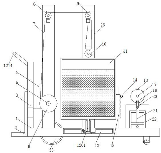
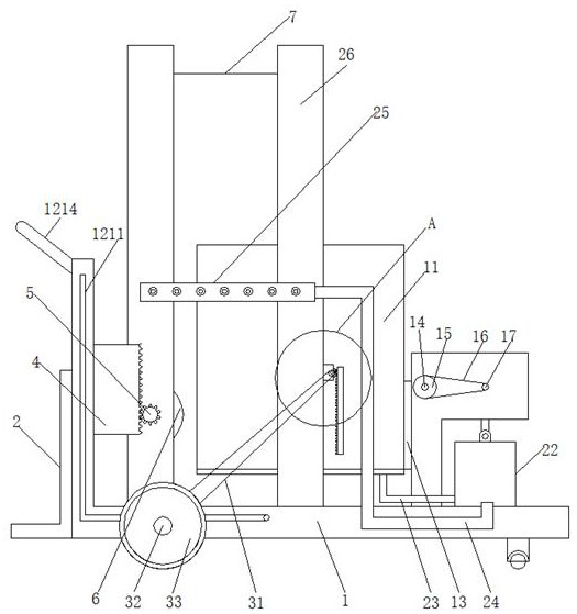
[0005] However, it is inconvenient to move the bridge deck concrete curing device for road bridge construction on the market at present. Two methods are usually used to move the bridge deck concrete curing device for road bridge construction. The device moves, but there is a large amount of water in the internal water tank of the health preservation device. It is difficult for the construction personnel to initially push the health preservation device, which is not convenient for the construction personnel to use the health preservation device for a long time; The transmission drives the health preservation device to move, but this method increases the weight and volume of the health preservation device itself, and will greatly increase the production cost of the health preservation device

Method used


Image

  • Concrete curing device for highway bridge construction bridge floor
  • Concrete curing device for highway bridge construction bridge floor
  • Concrete curing device for highway bridge construction bridge floor

Examples


Embodiment Construction

[0022] The following will clearly and completely describe the technical solutions in the embodiments of the present invention with reference to the accompanying drawings in the embodiments of the present invention. Obviously, the described embodiments are only some, not all, embodiments of the present invention. Based on the embodiments of the present invention, all other embodiments obtained by persons of ordinary skill in the art without making creative efforts belong to the protection scope of the present invention.

[0023] In the description of the present invention, it should be noted that the terms "center", "upper", "lower", "left", "right", "vertical", "horizontal", "inner", "outer" etc. The indicated orientation or positional relationship is based on the orientation or positional relationship shown in the drawings, and is only for the convenience of describing the present invention and simplifying the description, rather than indicating or implying that the referred d...


PUM


Abstract

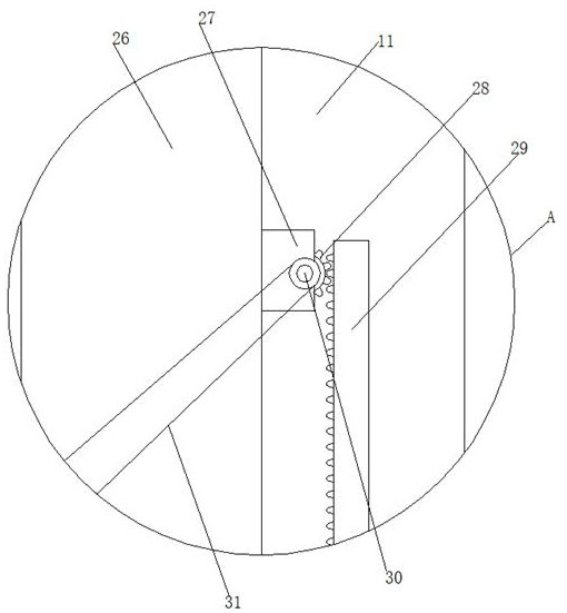
The invention discloses a concrete curing device for a highway bridge construction bridge floor, and relates to the field of highway bridge construction. The concrete curing device comprises a bearing seat, a standing plate is mounted at one side of the bearing seat, a connecting plate is arranged on the side, close to the bearing seat, of the standing plate and penetrates through the interior of the bearing seat, and a first clamping strip is mounted at the end, away from the standing plate, of the connecting plate; the outer wall of the first clamping strip is connected with a first gear column, and winding rollers are arranged at the two ends of the first gear column correspondingly. By arranging the bearing seat, the standing plate, a water tank, an adjusting mechanism and a sprinkler head, a limiting rod rotates to drive a connecting rod to move, so that a fourth piston plate is driven to do lifting reciprocating motion, and when the fourth piston plate ascends, water in the water tank is driven to flow into a piston box through a first corrugated pipe; when the fourth piston plate moves downwards, water in a piston box is pressed into the sprinkler head through a second corrugated pipe, so that the sprinkler head is used for curing the highway bridge construction bridge floor concrete.

Description

technical field [0001] The invention relates to the field of highway and bridge construction, in particular to a bridge deck concrete curing device for highway and bridge construction. Background technique [0002] Highway bridge engineering includes the main body of the bridge (namely, the bridge superstructure and the bridge substructure) and the auxiliary engineering facilities in the overall bridge position. There are many auxiliary engineering facilities, such as revetments and diversion dikes to regulate water flow in order to maintain the stability of the river channel at the bridge position The structure, the approach bridge connecting the bridge head with the road, the railings on the bridge to prevent wheel collisions, the sidewalk railings to ensure the safety of pedestrians, as well as the signs on the bridge, the navigation signs under the bridge and the lighting equipment on the bridge deck. The bridges in the area are also equipped with anti-vibration devices....

Claims


Application Information

Patent Timeline
IPC IPC(8): E01D21/00E01D19/12E01D101/24
CPCE01D21/00E01D19/125E01D2101/24
Inventor 周东民程雪梅
Owner 安徽安能建设集团有限公司
Learn More