
Gas-air mixing device for combustion equipment

A technology of combustion equipment and mixing devices, applied in the direction of burners, combustion methods, combustion types, etc., can solve the problems of impossible expansion of air flow channels, increase of operating time and operating distance, high adjustment ratio, etc., to reduce manufacturing costs , improve the adjustment ratio, prevent unnecessary use of the effect

Active Publication Date: 2016-08-24
KYUNGDONG NAVIEN
View PDF6 Cites 0 Cited by
  • Summary
  • Abstract
  • Description
  • Claims
  • Application Information

AI Technical Summary

Problems solved by technology

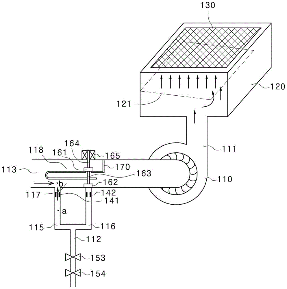
Therefore, when a larger air inflow is required, it is impossible to enlarge the air flow channel (118), and thus a high turndown ratio cannot be achieved
[0018] In addition, the long range of up and down motion of the rod (163) increases the stroke, resulting in increased operating time and operating distance

Method used


Image

  • Gas-air mixing device for combustion equipment
  • Gas-air mixing device for combustion equipment
  • Gas-air mixing device for combustion equipment

Examples


Embodiment Construction

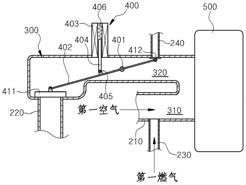
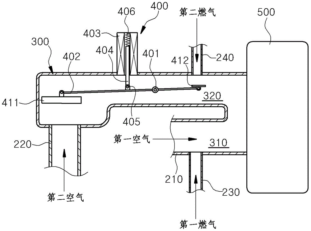
[0035] Hereinafter, exemplary embodiments of the present invention will be described with reference to the accompanying drawings. The embodiments of the present invention may be transformed into various forms, and it should be understood that the scope of the present invention is not limited to the embodiments for which the detailed description is provided below. The following examples provide those skilled in the art with a more detailed illustration of the present invention. Therefore, in the drawings, the shapes of elements may be exaggerated for a clearer understanding of the description. Identical or corresponding elements in each figure may be designated by the same reference numerals. Also, descriptions of known functions or constructions determined to obstruct understanding of the present invention are omitted.

[0036] Hereinafter, exemplary embodiments of the gas-air mixing device for combustion equipment of the present invention will be described in detail with re...


PUM


Abstract

The present invention relates to a gas-air mixing device for combustion equipment, and more particularly to a gas-air mixing device for combustion equipment that can effectively control the The amount of gas and air for the burner, thus increasing the turndown ratio, resulting in increased convenience of using hot water and heating, and increasing the life of the burner. The present invention comprises: a casing, one side of which is connected with a turbofan and provided with a predetermined space inside which gas and air can flow through; The path of the intake air from the outside is composed of a first air supply part and a second air supply part; a gas supply unit is composed of a first gas supply part and a second gas supply part, which are used to supply and gas mixed with air sucked by the air supply unit through paths different from each other; and an opening / closing device which closes the second air supply part and the second gas supply part to prevent air and gas flow, and open the second air supply and the second gas supply when a large amount of heat is required. According to the present invention, the adjustment ratio can be increased and the stroke of the solenoid valve can be shortened.

Description

technical field [0001] The present invention relates to a gas-air mixing device for combustion equipment, and more particularly, to a gas-air mixing device for combustion equipment that can efficiently control the supply to a gas-fired device provided in a combustion equipment such as a boiler or a water heater, etc. The amount of gas and air for the burner, thus increases the turndown ratio, resulting in increased convenience in using hot water and heating, and increased burner life. Background technique [0002] Generally, combustion equipment such as boilers or water heaters for hot water and heating are classified into oil-fired boilers, gas-fired boilers, electric boilers, and water heaters according to the fuels they are supplied, and are diversifiedly developed to suit different installation uses. [0003] Among these combustion devices, in particular, gas boilers and water heaters generally use a gas burner (BunsenBurner) or a premixed burner (Premixed Burner) to bur...

Claims


Application Information

Patent Timeline
Patent Type & Authority Patents(China)
IPC IPC(8): F23D14/62F23D14/60F23N1/02
CPCF23N1/02F23D14/60F23D14/62F24H1/186F24H9/2035
Inventor 朴焌圭
Owner KYUNGDONG NAVIEN
Learn More