Aero-engine braking device and aero-engine

An aero-engine and braking device technology, applied in the field of aero-engines, can solve the problems of low-pressure shaft fracture, rupture, puncture, damage, etc., and achieve the effect of effective braking, avoiding secondary accidents and improving safety.

Active Publication Date: 2022-07-12
AECC COMML AIRCRAFT ENGINE CO LTD
View PDF6 Cites 0 Cited by
  • Summary
  • Abstract
  • Description
  • Claims
  • Application Information

AI Technical Summary

Problems solved by technology

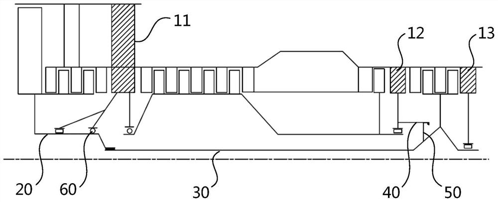
[0002] At present, most turbofan engines adopt a double-rotor structure. The low-pressure rotor includes a fan rotor and a low-pressure turbine rotor. The axial force on the fan rotor is forward, and the axial force on the low-pressure turbine rotor is backward. The axial force is backward, and the low-pressure shaft (including the fan shaft and the low-pressure turbine shaft) is a slender structure. Due to the existence of potential risks such as manufacturing defects, friction between the high and low pressure rotors, and seizure caused by foreign objects sucked by the fan, the low-pressure shaft There is a possibility of breaking
After the low-pressure shaft is broken, the aerodynamic force will not weaken immediately, and the speed of the low-pressure turbine will increase sharply after losing the load. If there is no effective braking structure, the speed of the low-pressure turbine will instantly exceed the limit value, which may cause the disk of the low-pressure turbine to rupture and break through. The low-pressure turbine casing, nacelle, and even the wings and passenger compartment are extremely harmful, so it is necessary to design a braking device to prevent the low-pressure turbine from exceeding the limit value

Method used


Image

  • Aero-engine braking device and aero-engine
  • Aero-engine braking device and aero-engine
  • Aero-engine braking device and aero-engine

Examples


Embodiment Construction

[0039] The technical solutions in the embodiments will be clearly and completely described below with reference to the accompanying drawings in the embodiments of the present invention. Obviously, the described embodiments are only some, but not all, embodiments of the present invention. Based on the embodiments of the present invention, all other embodiments obtained by those of ordinary skill in the art without creative work fall within the protection scope of the present invention.

[0040] In the description of the present invention, it should be understood that the terms "center", "horizontal", "portrait", "front", "rear", "left", "right", "top", "bottom", " The orientation or positional relationship indicated by vertical, horizontal, top, bottom, inner, outer, etc. is based on the orientation or positional relationship shown in the drawings, and is only for the convenience of describing the present invention and The description is simplified rather than indicating or im...


PUM


Abstract

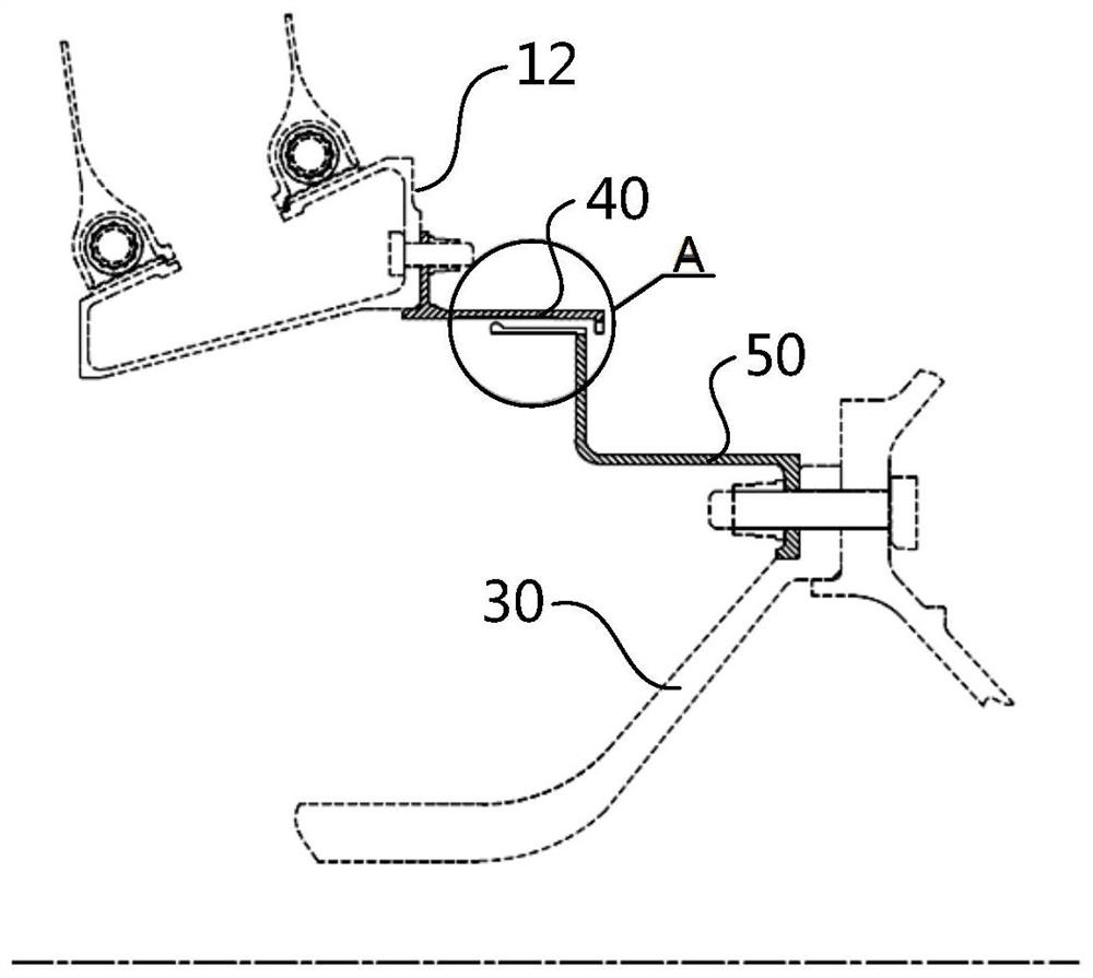
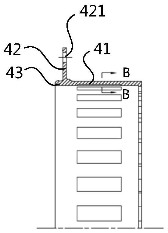
The invention relates to an aero-engine braking device and an aero-engine, wherein the aero-engine braking device comprises a load-bearing frame, a low-pressure shaft, a first braking member and a second braking member, the low-pressure shaft is connected with the load-bearing frame, and the low-pressure shaft is connected to the load-bearing frame. It includes a fan shaft and a low-pressure turbine shaft. The low-pressure turbine shaft is connected with the fan shaft and rotates relative to the load-bearing frame together with the fan shaft. The first braking member is arranged on the load-bearing frame, and the first braking member includes a first braking portion. and a second brake part, the first brake part is arranged on the side of the second brake part close to the fan shaft, the second brake part is arranged on the low pressure turbine shaft, and the second brake part includes a third brake part and a fourth braking part, the third braking part is arranged on the side of the fourth braking part close to the fan shaft. The aero-engine includes an aero-engine braking device. The braking form of the present invention is more abundant, the braking effect is more remarkable, and the safety of the engine is improved.

Description

technical field [0001] The invention relates to the technical field of aero-engines, in particular to an aero-engine braking device and an aero-engine. Background technique [0002] At present, most turbofan engines adopt a double-rotor structure. The low-pressure rotor includes a fan rotor and a low-pressure turbine rotor. The axial force on the fan rotor is forward, the axial force on the low-pressure turbine rotor is backward, and the low-pressure rotor as a whole is subjected to axial force. The axial force of the shaft is backward, and the low pressure shaft (including the fan shaft and the low pressure turbine shaft) is a slender structure. Due to manufacturing defects, friction between the high and low pressure rotors, and the existence of potential risks such as sticking caused by the inhalation of foreign objects by the fan, the low pressure shaft There is a possibility of breakage. After the low-pressure shaft is broken, the aerodynamic force will not be weakened ...

Claims


Application Information

Patent Timeline
Patent Type & Authority Patents(China)
IPC IPC(8): F02C7/00F02C7/32
CPCF02C7/00F02C7/32Y02T50/60
Inventor 黄云霞王国润朱文毅
Owner AECC COMML AIRCRAFT ENGINE CO LTD
Why Eureka
Try Eureka