Novel electric actuating mechanism
A technology of electric actuators and driving mechanisms, applied to engine components, devices to prevent accidental or unauthorized actions, mechanical equipment, etc., can solve problems such as lack of locking mechanisms, decreased valve accuracy, and changing valve openings , to avoid damage and avoid opening changes
- Summary
- Abstract
- Description
- Claims
- Application Information
AI Technical Summary
Problems solved by technology
Method used
Image

Examples
Embodiment
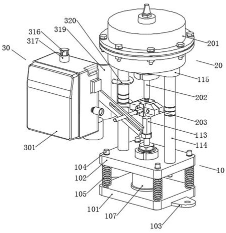
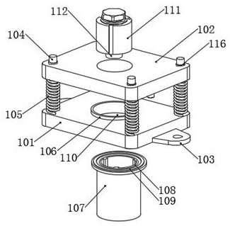
[0030] Example: see Figure 1-Figure 5 , a new type of electric actuator, including a mounting mechanism 10, a driving mechanism 20 fixed on the top of the mounting mechanism 10, and a locking mechanism 30 fixed on the top side of the mounting mechanism 10; The upper mounting seat 102 above the mounting seat 101 and the outer sides of the lower mounting seat 101 are provided with mounting ears 103 for connecting with the valve. It is welded with the lower mounting base 101, the vertical rod 104 runs through the upper mounting base 102, and the top outer side of the vertical rod 104 is provided with a second rubber sleeve 116, and the second rubber sleeve 116 runs through the upper mounting base 102 and is connected with the upper mounting base 102. The second rubber sleeve 116 is made of soft rubber material, and the vertical rod 104 can slide along the second rubber sleeve 116. Buffer springs 105 are sheathed on the outside, and both ends of the buffer springs 105 are fixedl...
PUM
 Abstract
Description
Claims
Application Information
PatSnap Eureka turns technology decisions into work you can execute. Powered by our Innovation Knowledge Graph, it runs expert workflows across engineering, life sciences, materials and intellectual property. Get your review-ready output in minutes.


