
Display panel and preparation method thereof

A technology for display panels and substrates, used in semiconductor/solid-state device manufacturing, instruments, electrical components, etc., can solve problems such as metal residues, and achieve the effect of reducing metal residues, reducing metal residues, and unaffected electrical properties.

Active Publication Date: 2021-06-29
WUHAN CHINA STAR OPTOELECTRONICS SEMICON DISPLAY TECH CO LTD
View PDF5 Cites 0 Cited by
  • Summary
  • Abstract
  • Description
  • Claims
  • Application Information

AI Technical Summary

Problems solved by technology

[0003] The embodiment of the present application provides a display panel to solve the problem of metal residue in the second metal layer in the prior art due to the slope generated after the first metal layer is patterned question

Method used


Image

  • Display panel and preparation method thereof
  • Display panel and preparation method thereof
  • Display panel and preparation method thereof

Examples

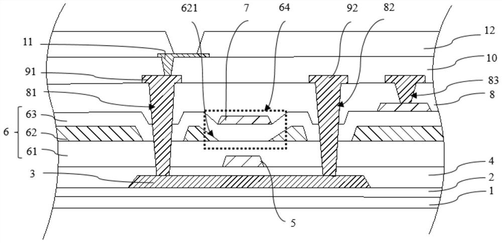

Embodiment Construction

[0025] The following will clearly and completely describe the technical solutions in the embodiments of the application with reference to the drawings in the embodiments of the application. Apparently, the described embodiments are only some of the embodiments of the application, not all of them. Based on the embodiments in this application, all other embodiments obtained by those skilled in the art without making creative efforts belong to the scope of protection of this application.

[0026] The present application provides a display panel, including a substrate, a first electrode, a composite insulating layer and a second electrode, wherein the composite insulating layer includes a first inorganic insulating layer, an organic insulating layer and a second inorganic insulating layer, and the organic insulating layer A groove is opened corresponding to the first electrode, so that the composite insulating layer forms a recess at the groove to accommodate the second electrode. ...


PUM

PropertyMeasurementUnit
thicknessaaaaaaaaaa
thicknessaaaaaaaaaa

Abstract

An embodiment of the invention discloses a display panel. The display panel comprises a substrate; a first electrode which is positioned on a first metal layer and is arranged on the substrate; a composite insulating layer which is arranged on the first metal layer and comprises a first inorganic insulating layer, an organic insulating layer and a second inorganic insulating layer, wherein a groove corresponding to the first electrode is formed in the organic insulating layer, and the composite insulating layer forms a concave part at the groove; and a second electrode which is positioned on the second metal layer and is arranged in the concave part. According to the display panel disclosed by the invention, the metal residue phenomenon of the second metal layer caused by patterning of the first metal layer can be remarkably reduced on the basis of not reducing the electrical property of the thin film transistor.

Description

technical field [0001] The present application relates to the field of display technology, in particular to a display panel and a manufacturing method thereof. Background technique [0002] In existing large-size display panels, such as figure 1 As shown, in order to reduce the current loss, metals with low resistivity such as Al or Ti are mostly used for the wiring of the first metal layer 1'. A metal layer 1' will form a relatively steep edge after patterning, so that the insulating layer 2' cannot be planarized when covering the first metal layer 1', so that the second metal layer 3' will be etched. Metal residues are generated on the insulating layer 2' on both sides of the first metal layer 1', which affects subsequent manufacturing processes. In order to solve this problem, the industry proposes to planarize the first metal layer 1' by increasing the film thickness of the insulating layer 2', but the increase of the insulating layer 2' will cause the first metal laye...

Claims


Application Information

Patent Timeline
Patent Type & Authority Applications(China)
IPC IPC(8): H01L27/12H01L21/84G09F9/33G09F9/35
CPCH01L27/124H01L27/1248H01L27/1259G09F9/33G09F9/35
Inventor 杨薇薇
Owner WUHAN CHINA STAR OPTOELECTRONICS SEMICON DISPLAY TECH CO LTD
Learn More