Method and device for in situ process monitoring

A process monitoring and in-situ technology, applied in the direction of measuring devices, optical devices, instruments, etc., can solve the problems of tedious calculation and data analysis, impossible and limited continuous operation

Pending Publication Date: 2021-06-29
UNIV OF BAYREUTH
View PDF7 Cites 1 Cited by
  • Summary
  • Abstract
  • Description
  • Claims
  • Application Information

AI Technical Summary

Problems solved by technology

[0013] A disadvantage of all mentioned methods and devices is that a real-time response of the signal is not possible due to the cumbersome computational data analysis required
Furthermore, continuous operation is not possible due to the physically limited computer memory of the measurement data

Method used


Image

  • Method and device for in situ process monitoring
  • Method and device for in situ process monitoring
  • Method and device for in situ process monitoring

Examples


Embodiment Construction

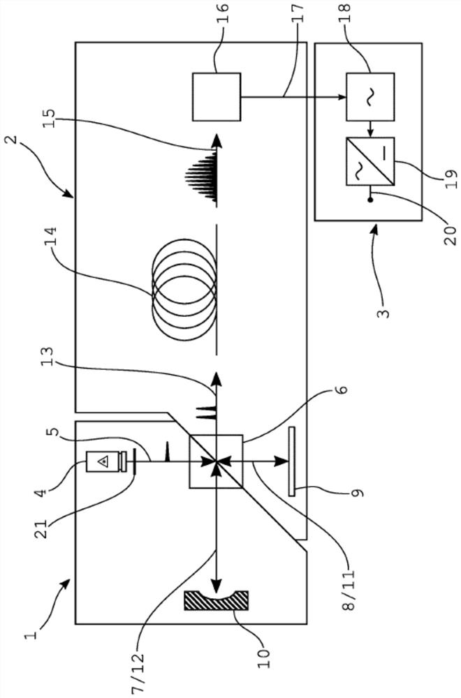
[0054] figure 1 The overall operation of the invention is provided and key elements of a method for enabling in situ process monitoring during laser processing and / or ablation are shown. A technical implementation of this method is also shown.

[0055] In principle, the overall application consists of three parts: material handling unit 1, measurement unit 2 and control unit 3.

[0056] The material handling unit 1 provides an operating beam which processes a target object 10 . An ultrashort pulse laser beam 5 is emitted by an ultrashort pulse laser 4 .

[0057] The ultrashort pulse laser 4 can emit pulses at a pulse interval which is longer than the duration of the tensile measurement signal of the interference beam 15 . In this case, the pulse interval is in the range of about 1 ns to 20 ns.

[0058] In another embodiment, the ultrashort pulse laser 4 emits equidistant laser pulses.

[0059] In one advantageous application, the pulse duration is in the range of nanoseco...


PUM


Abstract

This invention relates to a method and a device for in situ process monitoring and control down to a single pulse measurement during laser processing, like ablation, laser printing additive manufacturing and modification of refractive index. The application relates to laser material processing and to an integrated process monitoring using interference effects of a laser beam or laser pulse.

Description

[0001] invention technology [0002] The invention relates to a method and device for fast process monitoring by means of a pulsed laser using single pulse measurement at a high repetition rate. It allows in situ process monitoring and control of high repetition rate single pulse measurements during in situ inspection and / or detection of the laser. technical field [0003] The present application relates to in situ inspection and / or detection by means of lasers and to integrated process monitoring utilizing the spectral interference effect of laser pulses. Background technique [0004] Since the invention involving the amplification of light by stimulating the emission of radiation ("lasers" for short), a wide variety of applications from measurement to processing have been developed. The physical properties of laser light, together with interferometry, allow for extremely precise analysis and processing. With the help of extremely short and broadband light pulses from ult...

Claims


Application Information

Patent Timeline
Patent Type & Authority Applications(China)
IPC IPC(8): G01B9/02
CPCG01B9/02014G01B9/02084B23K26/032B23K26/0624B23K26/36
Inventor G·赫林克
Owner UNIV OF BAYREUTH
Why Eureka
Try Eureka