Actively-driven ankle joint artificial limb

An active drive, ankle joint technology, applied in the field of prosthetics, can solve the problems of complex, high cost and large volume of active ankle joints, and achieve the effects of light weight, light use and easy control

Inactive Publication Date: 2021-07-02
JILIN UNIV
View PDF6 Cites 0 Cited by
  • Summary
  • Abstract
  • Description
  • Claims
  • Application Information

AI Technical Summary

Problems solved by technology

As a commonly used electric drive element, the motor has the disadvantages of large size and high cost, and the traditional transmi

Method used


Image

  • Actively-driven ankle joint artificial limb
  • Actively-driven ankle joint artificial limb
  • Actively-driven ankle joint artificial limb

Examples


Embodiment Construction

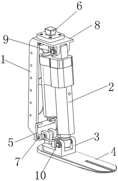
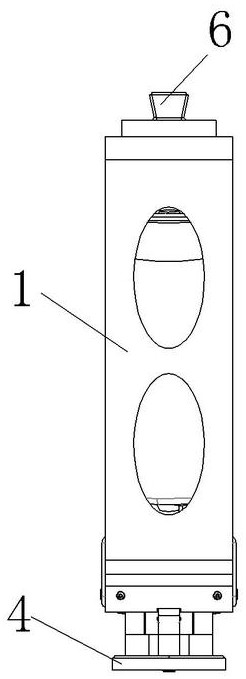
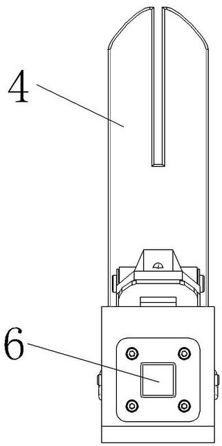
[0019] see Figure 1 to Figure 8 As shown, an actively driven ankle joint prosthesis includes a main frame 1, an electric linear driver 2, a foot plate connecting frame 3, a foot plate 4, a torsion spring 5 and a square platform 6; the foot plate connecting frame 3 is fixed on the upper surface of the foot plate 4 The bottom of the main frame 1 is hinged with the rear end of the foot plate connecting frame 3 through the ankle joint rotating shaft 7, the top of the main frame 1 extends forward with a platform 8, and a square platform 6 is installed on the platform 8, and the square platform 6 is used for Connected with the leg structure; the top of the electric linear driver 2 is hinged with the front lower part of the platform 8 through the first rotating shaft 9, and the lower end of the electric linear driver 2 is hinged with the front of the foot plate connecting frame 3 through the second rotating shaft 10; the ankle joint The rotating shaft 7 is sleeved with a torsion spr...


PUM


Abstract

The invention provides an actively-driven ankle joint artificial limb, which comprises a main rack, an electric linear driver, a foot plate connecting frame, a foot plate, a torsional spring and a quadrangular frustum pyramid, wherein the foot plate connecting frame is fixed to the heel portion of the upper surface of the foot plate, the bottom of the main rack is hinged to the rear end of the foot plate connecting frame through an ankle joint rotating shaft, the top of the main rack extends forwards to form a platform, the quadrangular frustum pyramid is installed on the platform and used for being connected with a leg structure, the top end of the electric linear driver is hinged to the front lower portion of the platform through a first rotating shaft, the lower end of the electric linear driver is hinged to the front portion of the foot plate connecting frame through a second rotating shaft, the ankle joint rotating shaft is sleeved with the torsional spring, and the two ends of the torsional spring abut against the inner side face of the main rack and the upper surface of the foot plate connecting frame respectively. According to the invention, the actively-driven ankle joint artificial limb is simple in structure, light in weight, convenient to use and easy to control; and the foot plate connecting frame connected with the electric linear driver rotates around the ankle joint rotating shaft by controlling the telescopic stroke of the electric linear driver, and then knee joint artificial limb bending of an amputated patient after the amputated patient is matched with the artificial limb is achieved.

Description

technical field [0001] The invention relates to the field of artificial limbs, in particular to an actively driven ankle joint artificial limb. Background technique [0002] As a walking rehabilitation aid, lower limb prosthetics have been widely used in patients with lower limb amputations. As an important part of prosthetics, the ankle joint plays a key role in human walking. Prosthetic ankle joints can generally be divided into passive type and active type. Passive ankle joints are generally single-axis ankle joints or universal ankle joints. Passive ankle joints do not have the ability to autonomously adjust gait and cannot supply energy. Sometimes the energy consumption increases and the gait appears asymmetric; the active ankle joint refers to the ankle joint that can provide additional energy supply. Generally, according to the energy source, it can be divided into electric drive, hydraulic or pneumatic type, which can reduce the energy consumption of amputee and pro...

Claims


Application Information

Patent Timeline
IPC IPC(8): A61F2/66A61F2/70
CPCA61F2/6607A61F2/68A61F2002/701
Inventor 任雷修豪华王旭钱志辉任露泉
Owner JILIN UNIV
Why Eureka
Try Eureka