A nursing device for emergency transfer of critically ill patients

A nursing device and patient technology, applied in the field of medical care, can solve the problems of hypothermia in various parts of the trunk, limited body temperature regulation mechanism, and patients who are not prone to hypothermia, so as to improve safety performance, avoid further deterioration, and promote accelerated blood circulation The effect of normal circulation

Active Publication Date: 2022-03-08
JILIN UNIV
View PDF7 Cites 0 Cited by
  • Summary
  • Abstract
  • Description
  • Claims
  • Application Information

AI Technical Summary

Problems solved by technology

[0002] At present, when emergency transfer of critically ill patients is carried out, the patient needs to be placed flat on the corresponding transfer bed, and lying flat for a long time will cause the patient's systemic blood circulation to slow down, because the body's blood supply is not timely and sufficient, it is easy to cause The various functions of the patient deteriorate, leading to further deterioration of the condition. In addition, due to the poor physical fitness of critically ill patients, their body temperature regulation mechanism is limited, and the various parts of the trunk are more susceptible to external influences and hypothermia, which in turn will aggravate the patient's morbidity. pain
[0003] Aiming at the deficiencies of the prior art, the present invention provides a nursing device for emergency transfer of critically ill patients, which has the advantages of effectively avoiding the further deterioration of the patient's condition and effectively avoiding the occurrence of hypothermia in the patient, and solves the problem of general During the use of emergency transfer equipment for critically ill patients, it cannot promote the patient's systemic blood circulation, which leads to further deterioration of the patient's condition, and the patient is prone to hypothermia during transfer

Method used


Image

  • A nursing device for emergency transfer of critically ill patients
  • A nursing device for emergency transfer of critically ill patients
  • A nursing device for emergency transfer of critically ill patients

Examples


Embodiment Construction

[0022] The following will clearly and completely describe the technical solutions in the embodiments of the present invention with reference to the accompanying drawings in the embodiments of the present invention. Obviously, the described embodiments are only some, not all, embodiments of the present invention. Based on the embodiments of the present invention, all other embodiments obtained by persons of ordinary skill in the art without making creative efforts belong to the protection scope of the present invention.

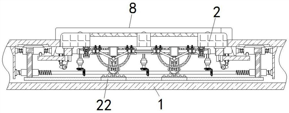
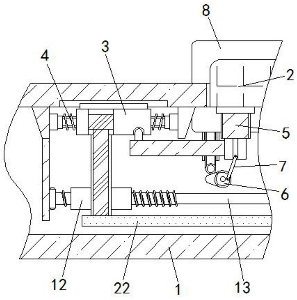
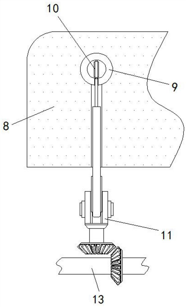
[0023] see Figure 1-4 , a nursing device for emergency transfer of critically ill patients, comprising a bed board 1, the upper wall of the bed board 1 is slidably connected with a pressure receiving plate 2, and the pressure receiving board 2 is provided with a rectangular groove adapted to a magnetic frame 15, and the rectangular groove The top of the bed is fixedly connected with a sponge layer. Before the transfer, the patient is placed flat on the surfac...


PUM


Abstract

The invention relates to the technical field of medical care, and discloses a nursing device for emergency transfer of critically ill patients. Inertial blocks are slidably connected to the left and right sides of the bed, abutting springs are fixedly connected between the inertia blocks and the inner wall of the bed board, and U-shaped extending to the inertia blocks are fixedly connected to the left and right sides of the lower end of the pressure-receiving plate. The front wall and the rear wall of the inner cavity of the bed board are rotatably connected with cams. The nursing device for emergency transfer of critically ill patients, the inertia block is no longer limited by the pressure plate being pressed down by gravity, and the inertia block can provide driving force during the transfer to drive the threaded tooth rod and tooth plate to move, so that the massage wheel It fits the patient's back movement, and makes the electric heating tank blow out hot air, thereby effectively avoiding the further deterioration of the patient's condition and effectively avoiding the occurrence of the patient's hypothermia.

Description

technical field [0001] The invention relates to the technical field of medical care, in particular to a nursing device for emergency transfer of critically ill patients. Background technique [0002] At present, when emergency transfer of critically ill patients is carried out, the patient needs to be placed flat on the corresponding transfer bed, and lying flat for a long time will cause the patient's systemic blood circulation to slow down, because the body's blood supply is not timely and sufficient, it is easy to cause The various functions of the patient deteriorate, leading to further deterioration of the condition. In addition, due to the poor physical fitness of critically ill patients, their body temperature regulation mechanism is limited, and the various parts of the trunk are more susceptible to external influences and hypothermia, which in turn will aggravate the patient's morbidity. pain. [0003] Aiming at the deficiencies of the prior art, the present invent...

Claims


Application Information

Patent Timeline
Patent Type & Authority Patents(China)
IPC IPC(8): A61H15/02A61F7/00A61G1/02A61G1/04
CPCA61H15/02A61H15/0078A61F7/007A61G1/02A61G1/04A61H2015/0028A61H2201/0142
Inventor 马莉王蕊蔡郁
Owner JILIN UNIV
Why Eureka
Try Eureka