Needle separating and sub-packaging equipment for waste syringes
A syringe and needle technology, applied in the field of needle separation and packaging equipment, can solve the problem of unremoved needles and achieve the effect of avoiding accidental injury
- Summary
- Abstract
- Description
- Claims
- Application Information
AI Technical Summary
Problems solved by technology
Method used
Image

Examples
Embodiment Construction
[0023] The present invention will be described in further detail below in conjunction with the accompanying drawings and embodiments. Wherein the same components are denoted by the same reference numerals. It should be noted that the words "front", "rear", "left", "right", "upper" and "lower" used in the following description refer to the directions in the drawings, and the words "bottom" and "top ”, “inner” and “outer” refer to directions toward or away from the geometric center of a particular part, respectively.
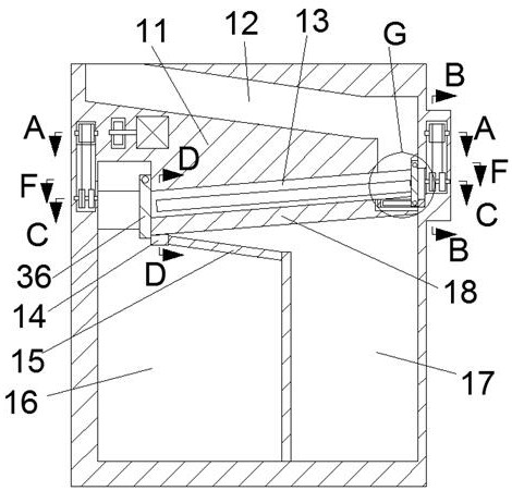
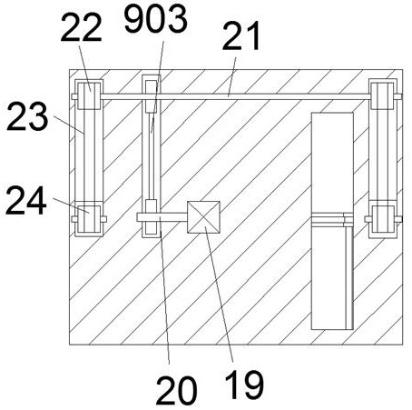
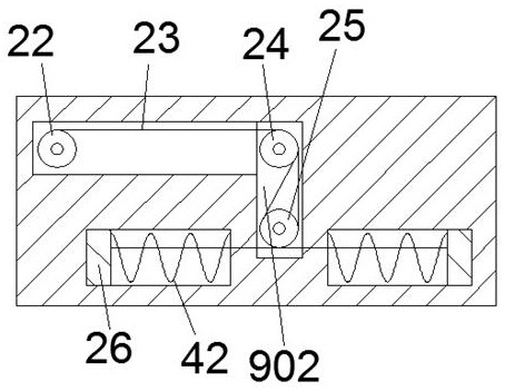
[0024] Such as Figures 1 to 9 As shown, a needle separation and packaging equipment for waste syringes includes a collection container 11, and a separation chamber 13 is provided in the collection container 11, and a separation chamber 13 is provided in the separation chamber 13 to make the separation chamber 13 face both sides. A separation mechanism for aligning the syringe and pulling the needle from the syringe, the separation mechanism includes a push-pull...
PUM
 Abstract
Description
Claims
Application Information