
Automatic detection system for surface defects of workpieces

A workpiece surface, automatic detection technology, applied in sorting and other directions, can solve the problems of high manual detection cost and insufficient automation level, and achieve the effect of avoiding errors, fully automation, and reducing labor costs.

Active Publication Date: 2021-07-02
慕贝尔汽车部件(太仓)有限公司
View PDF9 Cites 0 Cited by
  • Summary
  • Abstract
  • Description
  • Claims
  • Application Information

AI Technical Summary

Problems solved by technology

[0003] The invention provides an automatic detection system for workpiece surface flaws, which solves the problems in the prior art that the automatic level of workpiece flaw detection is insufficient and the cost of manual detection is high

Method used


Image

  • Automatic detection system for surface defects of workpieces
  • Automatic detection system for surface defects of workpieces
  • Automatic detection system for surface defects of workpieces

Examples


no. 1 approach

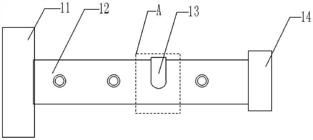
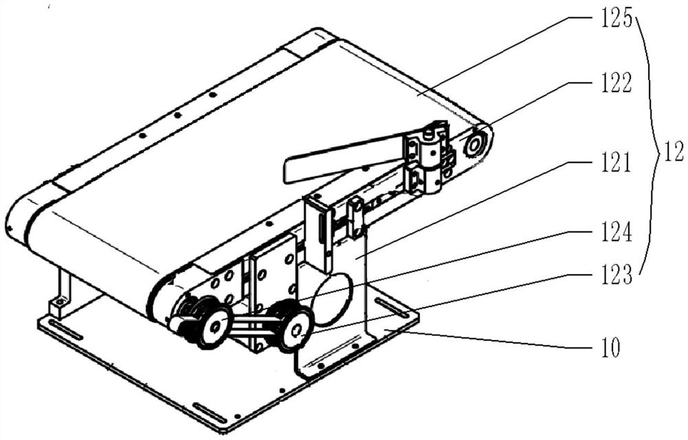
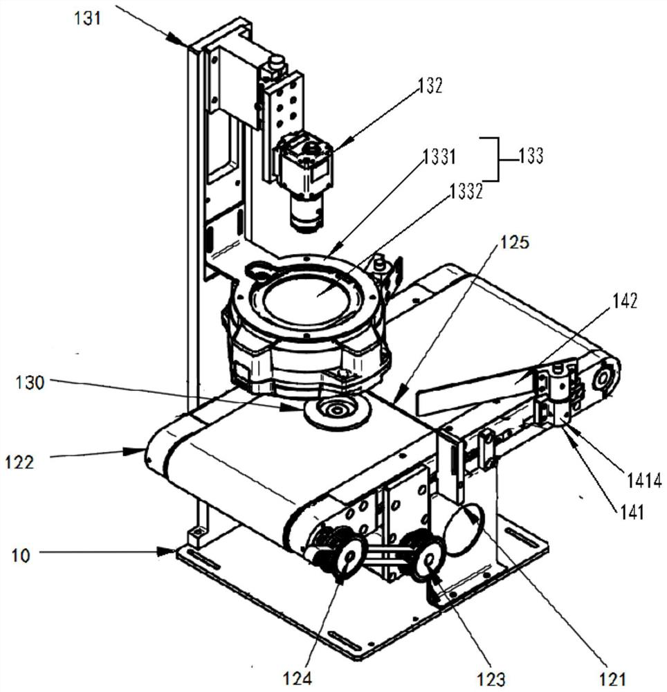
[0047] Such as figure 1As shown, the present invention provides an automatic detection system for workpiece surface defects, which includes a feeding device 11 , a conveying device 12 , an automatic detection device 13 and a sorting device 14 . The feeding device 11 is used for vibrating feeding, and the workpiece is placed on the transmission start end of the transmission device 12; the transmission device 12 is used to transmit the workpiece placed by the feeding device 11 from the transmission start end to the transmission end, And through to the preset area A corresponding to the automatic detection device 13, the preset area A is a preset fixed area on the transmission device 12; the automatic detection device 13 is located above the transmission device 12 for When the workpiece conveyed on the conveying device 12 reaches the preset area A, the workpiece surface flaws are automatically detected on the workpiece, and the defect detection result information is output; the s...

no. 2 approach

[0094] The second embodiment of the present invention provides an automatic detection system for workpiece surface blemishes, such as Figure 6 As shown, the automatic detection system for workpiece surface defects includes a feeding device 21, a first transmission device 22, a first automatic detection device 23, a turning device 24, a second transmission device 25, a second automatic detection device 26 and a sorting device 27 .

[0095] Wherein the structure of the feeding device 21 is the same as that of the first embodiment, the first conveying device 22 is used to transport the workpiece from the conveying starting end (left end) to the conveying end (right end), and the second conveying device 25 is used for The workpiece is transported from the transmission starting end (right end) to the transmission end (left end), the first transmission device 22 is provided with a first preset area A, and the second transmission device 25 is provided with a second preset area B; th...


PUM


Abstract

The invention belongs to the field of automatic detection of defects, and provides an automatic detection system for surface defects of workpieces in order to solve the problem that the automatic level of defect detection of the workpieces is insufficient. The automatic detection system comprises a feeding device, a conveying device, an automatic detection device and a sorting device, wherein the feeding device is used for feeding in a vibrating mode and placing the workpieces at the conveying starting end of the conveying device; the conveying device is used for conveying the workpieces placed by the feeding device from the conveying starting end to the conveying tail end and enabling the workpieces to pass through a preset area corresponding to the automatic detection device, and the preset area is a preset fixed area on the conveying device; the automatic detection device is located above the conveying device and used for automatically detecting the surface defects of the workpieces when the workpieces conveyed on the conveying device reach the preset area and outputting defect detection result information; and the sorting device is located at the conveying tail end of the conveying device and used for correspondingly sorting the workpieces located at the tail end of the conveying device according to the defect detection result information output by the automatic detection device.

Description

technical field [0001] The invention belongs to the field of automatic detection of blemishes, in particular to an automatic detection system for surface blemishes of workpieces. Background technique [0002] For the inspection of workpieces in the production line, multiple workers generally inspect the defects. This work not only requires the inspectors to have rich work experience, but also requires the inspectors to maintain high-intensity attention. For workers who work continuously on the assembly line, it is easy Visual fatigue will easily lead to the decline of detection efficiency and detection accuracy, and the phenomenon of false detection and missed detection will inevitably occur. Moreover, with the regional adjustment of the world economy and the industrial transformation of the Chinese economy, labor costs are getting higher and higher, and manual inspection methods cannot meet the current high-speed, precise, and automated production requirements. Therefore, ...

Claims


Application Information

Patent Timeline
Patent Type & Authority Applications(China)
IPC IPC(8): B07C5/34B07C5/02B07C5/36
CPCB07C5/34B07C5/02B07C5/362
Inventor 丁启东郁雪峰仲伟王建波
Owner 慕贝尔汽车部件(太仓)有限公司
Learn More