Supercharge Your Innovation With Domain-Expert AI Agents!

Pipe burying device based on hard land in water conservancy project

A water conservancy project, hard technology, applied in the direction of earth mover/shovel, construction, etc., can solve the problems of low positioning accuracy and lack of water pipelines, so as to improve the positioning accuracy of operations, avoid internal blockage, and high construction efficiency Effect

Inactive Publication Date: 2021-07-02
广州市如云网络科技有限公司
View PDF0 Cites 0 Cited by
  • Summary
  • Abstract
  • Description
  • Claims
  • Application Information

AI Technical Summary

Problems solved by technology

[0003] The size of the trenches excavated in general water conservancy projects matches the corresponding water pipelines. The burial of water pipelines with a diameter of less than 200 mm usually does not use machinery, but in the excavation of trenches, when hard ground is encountered , there is a lack of effective special machinery in water conservancy engineering equipment, a

Method used


Image

  • Pipe burying device based on hard land in water conservancy project
  • Pipe burying device based on hard land in water conservancy project
  • Pipe burying device based on hard land in water conservancy project

Examples


Example Embodiment

[0026] Example 1: See Figure 1 - Figure 6 The present invention is specifically implemented, for example:

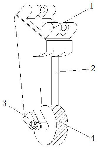
[0027] The present invention provides a bubble device based on hard land in a water conservancy engine, including a hinge block 1, a connecting frame 2, a motor box 3, a tank device 4, and the hinge block 1 is provided on the upper end of the connecting frame 2, and The hinge block 1 is integrated with the connecting frame 2, and an electric machine is disposed inside the motor box 3, the motor box 3 mounted on the left end of the connecting frame 2, the tank device 4 acting engaged in the inner wall of the connecting frame 2.

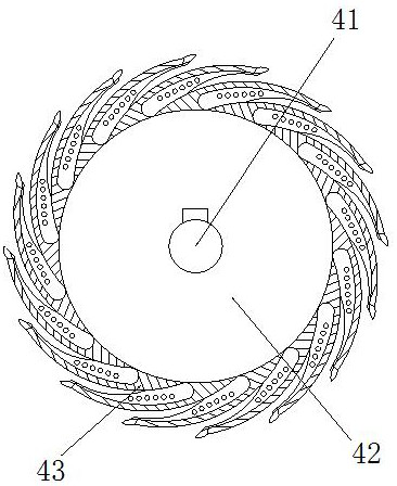
[0028] The tank device 4 is composed of a rotating shaft 41, a turntable 42, a cutter 43, and the rotating shaft 41 is actively engaged in the middle of the turntable 42, the rotating shaft 41 is connected to the motor strip provided in the motor box 3, the digging knife 43 There are a total of sixteen, and the sixteen of the cutter 43 is uniformly w...

Example Embodiment

[0034] Example 2: See Figure 7 - Figure 8 The present invention is specifically implemented, for example:

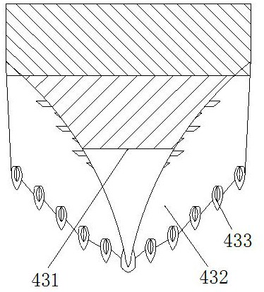
[0035] The present invention provides a buried tube device based on hard land in a water conservancy engine, which is composed of a tapered 331, a broken hammer 332, and a guiding angle 333, and the welding connection of the cone 331 has a broken sole hammer 332. The angle of the guide angle 333 is 70 degrees, and the conductive angle 333 is provided inside the cone 331, and the guiding angle 333 and the taper 331 are integrated structures, and the angle is 70-degree guiding angles 333. Easy to move the earth block to the outside.

[0036]The cutheme 332 is composed of a block 321, a pendulum 322, a fixed shaft 323, a first hammer head 324, and a second hammer head 325, and the lower end of the pendulum 322 is engaged inside the block 321 through the fixed shaft 323. The first hammer head 324 is a semi-circular spherical structure, and the first hammer head 324 is provided a...


PUM


Abstract

The invention discloses a pipe burying device based on hard land in a water conservancy project. The pipe burying device structurally comprises a hinge block, a connecting frame, a motor box and a grooving device; the hinge block is arranged at the upper end of the connecting frame, and the hinge block and the connecting frame are of an integrated structure; and a motor is arranged in the motor box, the motor box is mounted at the left end of the connecting frame, and the grooving device is movably clamped to the inner wall of the connecting frame. The grooving device can serve as a special machine for grooving in the water conservancy project, an excellent using effect is achieved for grooving of the hard land, and operation tools do not need to be replaced repeatedly; the width and depth of a groove can be controlled conveniently during construction, the construction efficiency is higher, and the operation positioning precision of a water conveying pipeline is greatly improved; and a soil breaking cone can preliminarily break soil blocks when piercing into the hard land, the size of the soil blocks is reduced, the preliminarily broken soil blocks are guided, and the situation that the grooving device is damaged due to internal blockage of the grooving device is avoided.

Description

technical field [0001] The invention relates to the field of water conservancy, and more specifically relates to a pipe-burying device based on hard soil in a water conservancy project. Background technique [0002] A water conservancy project is an operation that transports water from a low place to a high place. The water delivery pipeline in a water conservancy project is usually buried underground. The construction of the water delivery pipeline generally includes alignment, trench excavation, downpipe, interface, and soil covering. , pressure test, flushing, disinfection and site cleaning, etc., in order to improve the construction quality, reduce the construction cost, shorten the construction date as much as possible, and reduce the interference to the traffic, the pipeline burying construction should have good construction equipment, but the existing technology exists The following deficiencies: [0003] The size of the trenches excavated in general water conservanc...

Claims


Application Information

Patent Timeline
IPC IPC(8): E02F5/08E02F5/14E02F5/02
CPCE02F5/02E02F5/08E02F5/14
Inventor 陈妙翠
Owner 广州市如云网络科技有限公司
Features
  • R&D
  • Intellectual Property
  • Life Sciences
  • Materials
  • Tech Scout
  • Unparalleled Data Quality
  • Higher Quality Content
  • 60% Fewer Hallucinations
Learn More