Reinforcing structure for non-flush joints of outer vertical face of concrete frame structure

A frame structure and reinforcement structure technology, which is applied in the direction of building construction, construction, building maintenance, etc., can solve the problems of automatic reinforcement, no clamping position, and inability to assist cross-bar connection, etc., to achieve enhanced fixing effect and stable fixed installation Effect

Active Publication Date: 2021-07-02
DESIGN INST NO 9 MINISTRY OF MECHINE BUILDING
View PDF17 Cites 0 Cited by
  • Summary
  • Abstract
  • Description
  • Claims
  • Application Information

AI Technical Summary

Problems solved by technology

[0005] The purpose of the present invention is to provide a reinforcement structure for uneven joints on the facade of concrete frame structures, so as to solve the problem that the existing reinforcement structures for uneven joints of concrete frame structures cannot be automatically reinforced and fixed when they are in use, and cannot In the event of an earthquake, the fixing effect will be automatically strengthened, and the connection with the cross bar cannot be assisted, and when the reinforcement structure of the existing concrete frame structure with uneven joints is used, there is no clamping position, it cannot be clamped and fixed, and it cannot be effectively spliced ​​and strengthened fixed problem

Method used


Image

  • Reinforcing structure for non-flush joints of outer vertical face of concrete frame structure
  • Reinforcing structure for non-flush joints of outer vertical face of concrete frame structure
  • Reinforcing structure for non-flush joints of outer vertical face of concrete frame structure

Examples


Embodiment

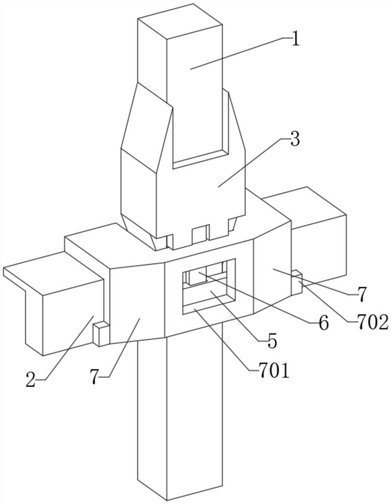
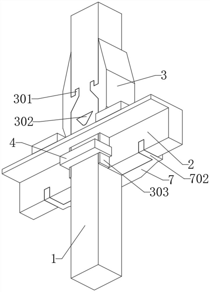
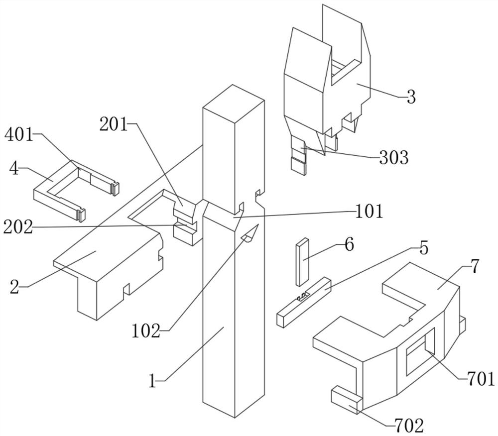
[0034] like Figure 1-Figure 8 As shown, the present invention is used for the reinforced structure of uneven joints on the facade of concrete frame structure, which is composed of main body 1, beam 2, force-bearing member 3, connector 4, fixing plate 5, control plate 6 and reinforcing member 7.

[0035] The main body 1 is a rectangular strip structure made of concrete material, and the main body 1 is embedded in the installation groove 201 of the beam 2 . The connecting piece 4 is inserted and installed inside the fixing groove 202 of the crossbeam 2 , at the middle position outside the connecting plate 303 of the force receiving member 3 . The top of the control board 6 is inserted into the rectangular groove of the force receiving member 3 , the bottom is inserted into the inner groove 502 of the fixed plate 5 , and a rectangular board is inserted into the control groove 601 of the control board 6 . The reinforcing piece 7 is set on the front end of the crossbeam 2 , the r...


PUM


Abstract

The invention provides a reinforcing structure for non-flush joints of the outer vertical face of a concrete frame structure, and belongs to the technical field of frame reinforcing. The reinforcing structure aims to solve the problems that when an existing reinforcing structure for the non-flush joints of the concrete frame structure is used, the fixing effect cannot be automatically enhanced when an earthquake occurs, and the reinforcing structure cannot be connected with a cross rod in an auxiliary mode. The reinforcing structure for the non-flush joints of the outer vertical face of the concrete frame structure comprises a main body, a cross beam and a stress piece, wherein the main body is of a rectangular long-strip-shaped structure made of concrete and is embedded into a mounting groove of the cross beam, the stress piece is installed on the outer side of the main body and is connected with a stress groove through an inserting block, so that the stress piece can be stably connected and fixed with the main body, and a connecting plate can be inserted into the mounting groove to be fixed by a connecting piece. The reinforcing structure can be stably installed, when the earthquake occurs, the stress piece can move towards the interior of the mounting groove, then the stress piece can be in contact with the mounting groove to be fixed, and then the fixing effect is automatically enhanced.

Description

technical field [0001] The invention belongs to the technical field of frame reinforcement, and more specifically relates to a reinforcement structure for uneven joints on the facade of a concrete frame structure. Background technique [0002] Reinforced concrete frame structure is one of the most common building structures in industrial and civil buildings, in which nodes play a role in distributing internal forces, coordinating component deformation and maintaining structural integrity in the structural load-bearing system. Under earthquake action, frame joints are prone to shear failure in the core area, and facade joints are more likely to occur. At this time, reinforcement structures are needed. [0003] The prior art discloses a reinforcement method and a reinforcement structure for uneven nodes on the facade of a concrete frame structure. The reinforcement method includes digging a main channel on the concrete protective layer in the core area of ​​the node. The core ...

Claims


Application Information

Patent Timeline
IPC IPC(8): E04G23/02
CPCE04G23/0218
Inventor 郭瑞顺柳青海杨雪洁
Owner DESIGN INST NO 9 MINISTRY OF MECHINE BUILDING
Why Eureka
Try Eureka