CO gas monitoring device for gas stove

A technology for monitoring devices and gas furnaces, applied in measuring devices, general control systems, and analyzing gas mixtures, can solve problems such as submersion, inability to monitor harmful gases, and potential safety hazards, and achieve the effect of avoiding CO poisoning

Inactive Publication Date: 2021-07-02
ANHUI SAIAN ANQUAN EQUIP
View PDF0 Cites 0 Cited by
  • Summary
  • Abstract
  • Description
  • Claims
  • Application Information

AI Technical Summary

Problems solved by technology

[0004] The object of the present invention is to provide a CO gas monitoring device for a coal-fired gas furnace. The CO concentration in the gas hood is detected by a CO detector. When the CO concentration exceeds the standard, the controller controls the lifting rod to lift the water collection tank until The water in the sump submerges the intake pipe, which solves the problem that the existing gas furnace cannot monitor harmful gases and has potential safety hazards

Method used


Image

  • CO gas monitoring device for gas stove

Examples


Embodiment Construction

[0025] The following will clearly and completely describe the technical solutions in the embodiments of the present invention with reference to the accompanying drawings in the embodiments of the present invention. Obviously, the described embodiments are only some, not all, embodiments of the present invention. Based on the embodiments of the present invention, all other embodiments obtained by persons of ordinary skill in the art without creative efforts fall within the protection scope of the present invention.

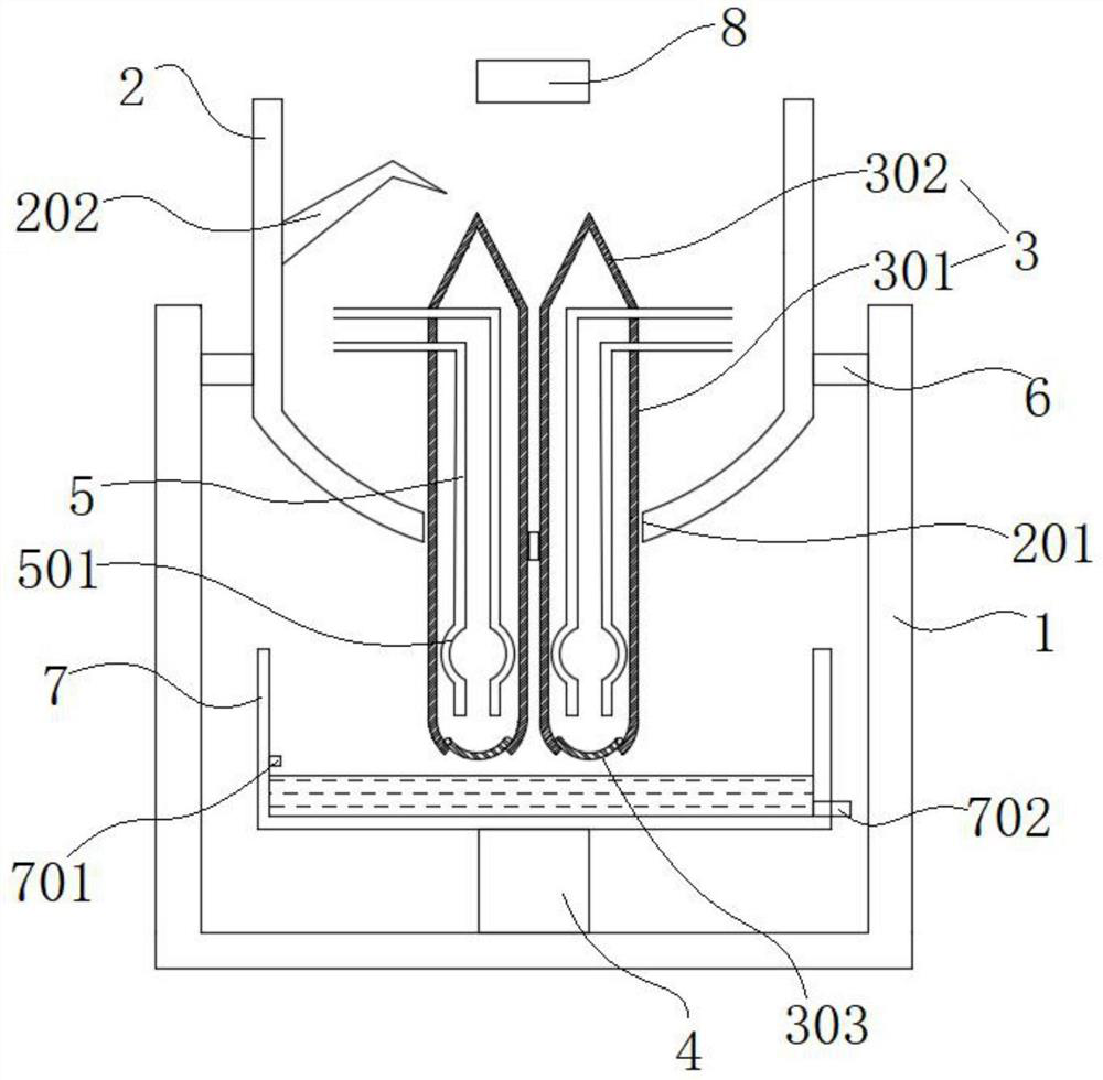
[0026] see figure 1 As shown, the present invention is a CO gas monitoring device for a gas-fired gas furnace, including a gas furnace 1 and a gas cover 2 arranged inside the gas furnace 1 from top to bottom, a water collection tank 7, a lifting rod 4 and a limiter. bitboard6;

[0027] A lifting rod 4 is fixedly installed at the bottom of the gas furnace 1;

[0028] The gas cover 2 is a cylindrical body; a CO detector 8 is installed above the inside of the gas co...


PUM


Abstract

The invention discloses a CO gas monitoring device for a gas furnace, and relates to the technical field of gas monitoring. The CO gas monitoring device comprises a gas stove, a gas hood, a water collecting tank, a lifting rod and a limiting plate, wherein a CO detector is mounted at the upper part in the gas hood; a gas device is fixedly mounted at the bottom of the gas hood; the gas device comprises a circular pipe and a conical pipe inversely arranged at the top end of the circular pipe; a sealing gasket is movably mounted at the bottom end of the circular pipe; a gas inlet pipeline is arranged in the circular pipe; the water collecting tank is fixed at the top end of the lifting rod; and a water level sensor is arranged on the inner wall of the water collecting tank. The CO concentration in the gas hood is detected through the CO detector, when the CO concentration exceeds the standard, the controller controls the lifting rod to lift the water collecting tank until water in the water collecting tank submerges the gas inlet pipeline, gas supply of the gas device can be cut off due to the fact that gas is insoluble in water, meanwhile, the controller closes a gas valve, more CO is prevented from being generated, and CO poisoning of a user is avoided.

Description

technical field [0001] The invention belongs to the technical field of gas monitoring, in particular to a CO gas monitoring device for a coal gas furnace. Background technique [0002] The gas generator is a device that converts coal into combustible gas and gas. In recent years, with the development of science and technology, the gas generator has been widely used in industrial heating, and its energy-saving and environmental protection effects, low cost, and heating performance have been improved. Fully affirmed by the majority of users. [0003] At present, with the improvement of people's living standards and the enhancement of environmental awareness, people began to choose clean, non-polluting gas-fired gas stoves, but the current gas-fired gas stoves still have many shortcomings, such as the number of fires that appear in the country every winter. A carbon monoxide poisoning incident, or a gas leakage incident caused by the accidental extinguishment of the fire, etc....

Claims


Application Information

Patent Timeline
Patent Type & Authority Applications(China)
IPC IPC(8): G01N33/00G05B19/048
CPCG01N33/004G05B19/048G05B2219/2612
Inventor 朱广朱永亮
Owner ANHUI SAIAN ANQUAN EQUIP
Why Eureka
Try Eureka