Wireless charging clamping mechanism and wireless charger

A technology of wireless charging and clamping mechanism, which is applied in the direction of current collectors, battery circuit devices, electric vehicles, etc., can solve problems such as the decline in charging efficiency, and achieve the effect of not being easy to shake and improving charging efficiency

Pending Publication Date: 2021-07-02
CHONGQING CHANGAN AUTOMOBILE CO LTD
View PDF4 Cites 0 Cited by
  • Summary
  • Abstract
  • Description
  • Claims
  • Application Information

AI Technical Summary

Problems solved by technology

Avoid the problem that mobile phones of different sizes slide when placed on the wirel

Method used


Image

  • Wireless charging clamping mechanism and wireless charger
  • Wireless charging clamping mechanism and wireless charger
  • Wireless charging clamping mechanism and wireless charger

Examples


Embodiment Construction

[0022] The present invention will be described in detail below with reference to the accompanying drawings.

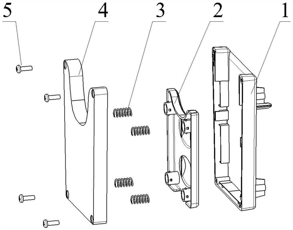
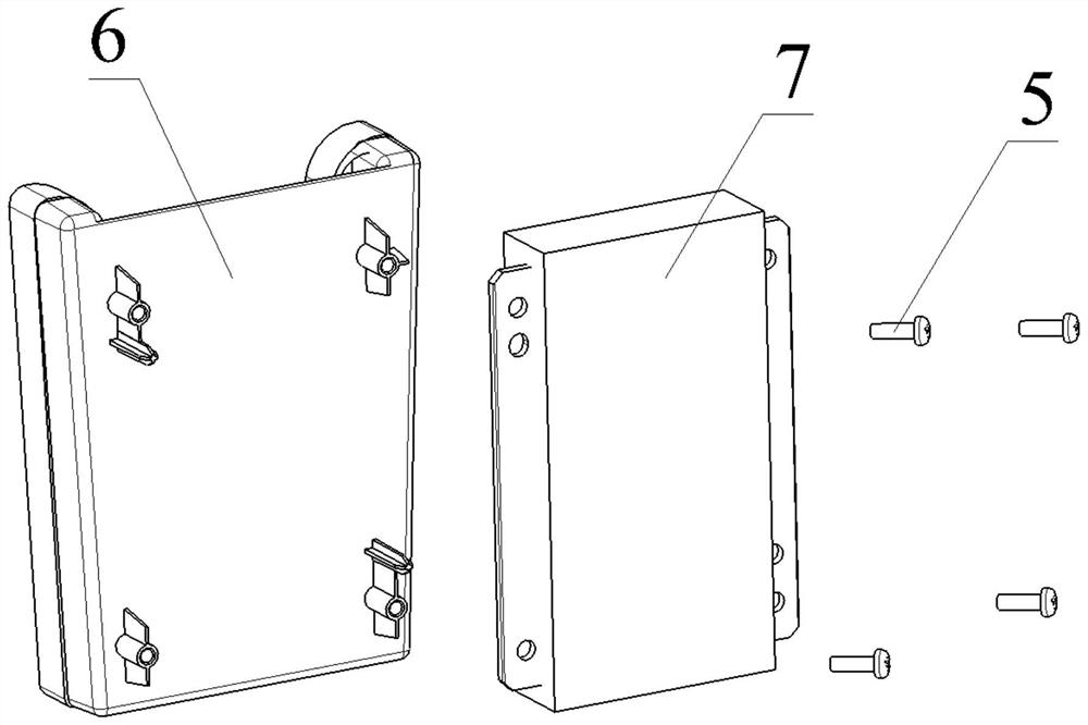
[0023] like Figure 1-Figure 8 As shown, the wireless charging clamping mechanism 6 disclosed in the present invention includes: a bottom case 1 , a clamping plate 2 and an upper cover 4 .

[0024] The bottom case 1 is face-to-face with the upper cover 4 and is fixed around by four mounting screws 5 . The bottom case 1 is used for fixed connection with the charging module 7 by means of mounting screws 5 .

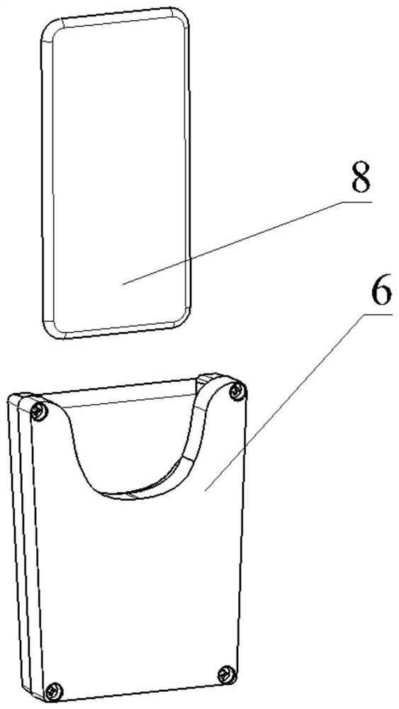
[0025] There is an oval notch in the direction of the mobile phone insertion opening of the upper cover 4. The mobile phone 8 is inserted from the mobile phone insertion opening above the upper cover 4. When placed, the front of the mobile phone 8 faces the direction of the upper cover 4, and the back of the mobile phone 8 with the wireless charging function faces the bottom shell 1. direction. There is an oval gap on the upper cover 4 of the wireless charging cl...


PUM


Abstract

The invention discloses a wireless charging clamping mechanism and a charger. The wireless charging clamping mechanism comprises a bottom shell, a clamping plate and an upper cover. The rubber material on the clamping plate is in contact with the surface of the mobile phone, and the mobile phone can be fixed without sliding down or shaking left and right after the mobile phone is inserted in place by means of the elastic force of the rubber and the displacement of the clamping plate. The elastic force formed by the deformation of the rubber on the clamping plate causes the reverse elastic force of the spring to the clamping plate, so that the clamping plate and the bottom shell form a cavity capable of accommodating mobile phones with different thicknesses, the thickness of the cavity can be changed along with the expansion and contraction of the spring, the mobile phones are ensured to be vertically placed and are not easy to shake, the optimal charging position is achieved, and the charging efficiency of the wireless charging device is improved.

Description

technical field [0001] The invention relates to an automobile wireless charging system, in particular to an installation and clamping mechanism of a wireless charging module. Background technique [0002] Most of the vehicle wireless charging modules in the prior art can only be assembled in the lower part of the instrument panel storage box, or inside the sub-instrument panel storage box, but the mobile phone can only be placed horizontally or at a small angle, so it is necessary to discard the instrument panel or the sub-instrument panel storage box. Part of the storage space of the instrument panel needs to have special requirements for the shape of the instrument panel and the sub-instrument panel. Moreover, when the mobile phone is placed horizontally or at a certain angle, the mobile phone is in a free state. During the driving or braking process, the mobile phone will move, causing the charging to be repeatedly disconnected, which in turn affects the charging efficien...

Claims


Application Information

Patent Timeline
IPC IPC(8): H02J7/00H02J50/90H02J50/00
CPCH02J7/0044H02J50/90H02J50/00Y02B40/00
Inventor 李永斌
Owner CHONGQING CHANGAN AUTOMOBILE CO LTD
Why Eureka
Try Eureka