
Tool for machining large-size thin-wall disc ring parts

A technology of ring parts and thin-walled discs, which is applied to the processing of large-size thin-walled disc ring parts on CNC vertical lathe, can solve the problems of increasing manufacturing costs, low practicability, and increasing costs, etc.

Pending Publication Date: 2021-07-06
SHANGHAI TOBACCO MACHINERY
View PDF0 Cites 1 Cited by
  • Summary
  • Abstract
  • Description
  • Claims
  • Application Information

AI Technical Summary

Problems solved by technology

[0002] In the processing process of CNC vertical lathe machine tools, it is necessary to design and build suitable tooling for large-scale thin-walled disc ring parts with high processing requirements in batch processing. This process takes a long time; at the same time, because the existing CNC vertical lathe chuck The claws installed on the top are all hard claws. During the clamping process, the claws are in point contact with the workpiece, and the supporting surface is small. Therefore, it is easy to cause the clamping deformation of the workpiece during processing, reduce the qualification of the product, and increase the manufacturing cost of the enterprise.
In addition, the chuck cannot replace the appropriate jaws with the change of the shape of the thin-walled part, which has low practicability and correspondingly increases the cost of the equipment required for processing

Method used


Image

  • Tool for machining large-size thin-wall disc ring parts
  • Tool for machining large-size thin-wall disc ring parts
  • Tool for machining large-size thin-wall disc ring parts

Examples


Embodiment Construction

[0036] The specific implementation manners of the present invention will be described in further detail below in conjunction with the accompanying drawings. These embodiments are only used to illustrate the present invention, not to limit the present invention.

[0037] In the description of the present invention, it should be noted that the orientations or positional relationships indicated by the terms "vertical", "horizontal", "top", "bottom", "inner" and "outer" are based on the The orientation or positional relationship is only for the convenience of describing the present invention and simplifying the description, but does not indicate or imply that the device or element referred to must have a specific orientation, be constructed and operated in a specific orientation, and therefore cannot be construed as limiting the present invention . In addition, the terms "first" and "second" are used for descriptive purposes only, and should not be understood as indicating or imp...


PUM


Abstract

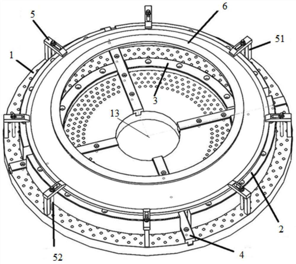
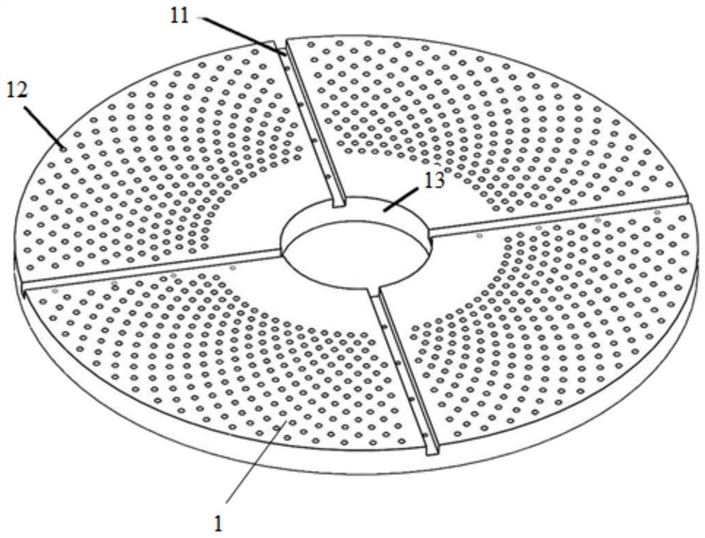
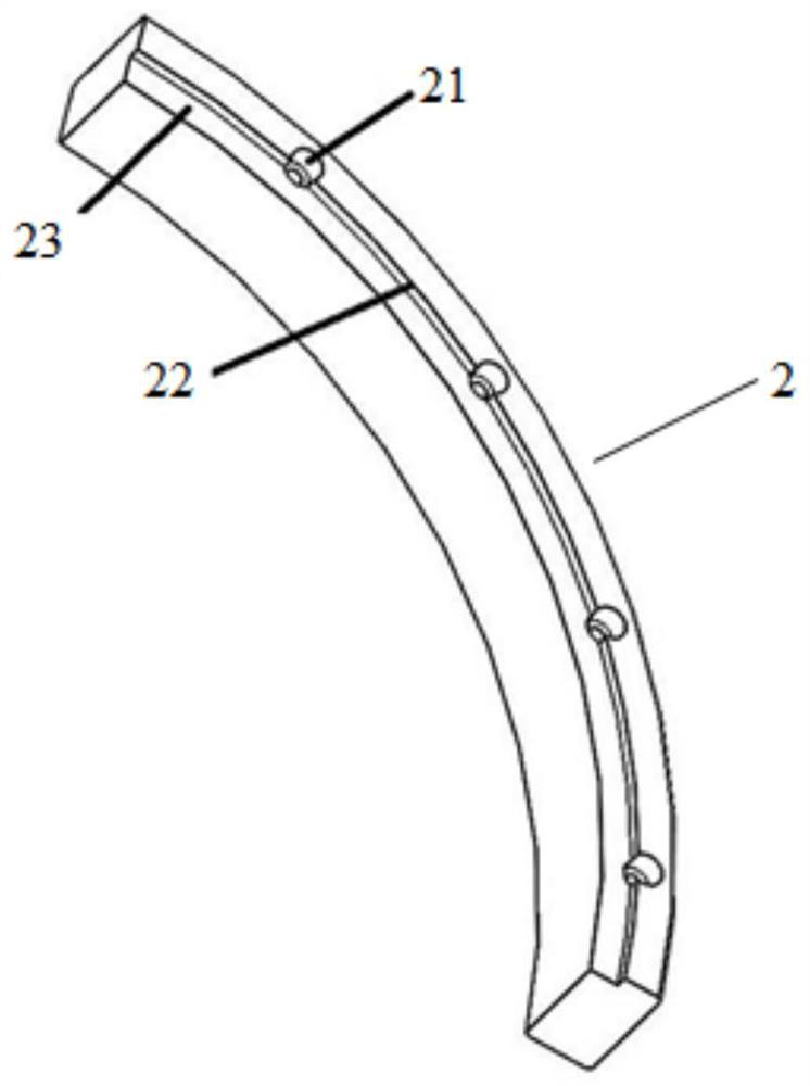
The invention provides a tool for machining large-size thin-wall disc ring parts. The tool comprises a bottom plate, a plurality of cushion blocks and a plurality of clamping pieces, wherein the bottom plate is circular, a through hole is formed in the circle center of the bottom plate, and a plurality of screw holes which are uniformly distributed along the radial direction are formed in the bottom plate; the cushion blocks are detachably connected with the bottom plate through the screw holes, and all the cushion blocks form an annular supporting part used for placing a workpiece; and each clamping piece comprises a pressing plate, and the pressing plates are used for pressing the workpiece on the supporting part. The tool has the beneficial effects that through the arrangement of the bottom plate on which the screw holes are uniformly distributed, an operator can mount the cushion blocks of different specifications on the bottom plate according to the appearances of different workpieces, so that the time consumed for designing and building the tool is shortened, and rapid positioning and clamping of the workpieces are realized. Meanwhile, the pressing plate is adopted to replace an existing clamping jaw, point contact is changed into surface contact, and therefore clamping deformation of the workpiece is effectively reduced, the percent of pass of parts is improved, and the manufacturing cost of an enterprise is reduced.

Description

technical field [0001] The invention relates to the technical field of processing large-size thin-walled disk ring parts on a numerically controlled vertical lathe, in particular to a tool for processing large-size thin-walled disk ring parts. Background technique [0002] In the processing process of CNC vertical lathe machine tools, it is necessary to design and build suitable tooling for large-scale thin-walled disc ring parts with high processing requirements in batch processing. This process takes a long time; at the same time, because the existing CNC vertical lathe chuck The claws installed on the machine are all hard claws. During the clamping process, the claws are in point contact with the workpiece, and the supporting surface is small. Therefore, it is easy to cause the clamping deformation of the workpiece during processing, reduce the qualification of the product, and increase the manufacturing cost of the enterprise. In addition, the chuck cannot replace the ap...

Claims


Application Information

Patent Timeline
Patent Type & Authority Applications(China)
IPC IPC(8): B23Q3/06
CPCB23Q3/065
Inventor 吴炜李晓刘洪瑞许俭孙元坤李姚朱怡珺
Owner SHANGHAI TOBACCO MACHINERY
Learn More