Adjustable pneumatic multifunctional screwdriver for constructional engineering
A kind of construction engineering and adjustable technology, which is applied in the direction of screwdrivers, motor tools, manufacturing tools, etc., can solve the problem that the screws cannot be screwed in place
- Summary
- Abstract
- Description
- Claims
- Application Information
AI Technical Summary
Problems solved by technology
Method used
Image
Examples
Embodiment 1
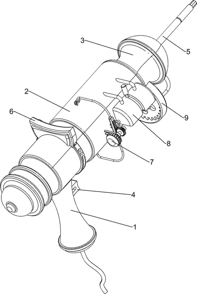
[0029] An adjustable pneumatic multifunctional screwdriver for construction engineering, such as figure 1 As shown, it includes a first frame body 1, a second frame body 2, a third frame body 3, a switch mechanism 4 and a rotation mechanism 5, and the rear side of the first frame body 1 is provided with a second frame body 2, and the second frame body 2 A third frame body 3 is provided on the rear side, a switch mechanism 4 is provided on the first frame body 1, and a rotation mechanism 5 is connected between the second frame body 2 and the third frame body 3.
[0030] When the user needs to use a screwdriver, the screwdriver can be used. The user can first connect the screwdriver to the air pump, then turn on the switch through the switch mechanism 4, and then start working through the rotating mechanism 5. When the user does not need to use the screwdriver, through The switch mechanism 4 can be closed.
Embodiment 2
[0032] On the basis of Example 1, such as figure 2 and image 3 As shown, the switch mechanism 4 includes a first isolation plate 41, a barrier ball 42, a linear spring 43 and a push switch 44. The lower side of the first frame body 1 is provided with a first isolation plate 41, and the first isolation plate 41 is provided with a slide type. There are two blocking balls 42 , the first frame body 1 is provided with a sliding push switch 44 , and a linear spring 43 is connected between the pressing switch 44 and the two blocking balls 42 .
[0033] The user can connect the air pump to the lower part of the first frame body 1. When the user needs to turn on the switch, he can press the push switch 44 to the inside, and the push switch 44 drives the barrier ball 42 to move forward, so that the two barrier balls 42 do not move forward. Block the first isolation plate 41 again, and now the linear spring 43 is compressed, so that the air pressure generated by the air pump enters th...
Embodiment 3
[0037] On the basis of Example 2, such as Figure 4-9 As shown, a flow control mechanism 6 is also included, and the flow control mechanism 6 includes a first connecting rod 61, a lower wedge 62, an upper wedge 63, a second isolation plate 64, a stopper 65 and a first placement frame 66, press The upper part of the switch 44 is provided with a first connecting rod 61, the upper part of the first connecting rod 61 is provided with a lower wedge-shaped block 62, the first frame body 1 is covered with a first placement frame 66, and the top of the first placement frame 66 is provided with a stopper 65 , the first placement frame 66 is slidingly provided with a second isolation plate 64 , the second isolation plate 64 is connected with an upper wedge block 63 , and the upper wedge block 63 cooperates with the lower wedge block 62 .
[0038] When the push switch 44 moves inwardly, it drives the first connecting rod 61 and the lower wedge 62 to move inwardly, so that the lower wedge 6...
PUM
 Abstract
Description
Claims
Application Information
 - R&D
- Intellectual Property
- Life Sciences
- Materials
- Tech Scout
- Unparalleled Data Quality
- Higher Quality Content
- 60% Fewer Hallucinations
Browse by: Latest US Patents, China's latest patents, Technical Efficacy Thesaurus, Application Domain, Technology Topic, Popular Technical Reports.
© 2025 PatSnap. All rights reserved.Legal|Privacy policy|Modern Slavery Act Transparency Statement|Sitemap|About US| Contact US: help@patsnap.com


