Machine head assembly of cutting machine

A cutting machine and machine head technology, applied in metal processing and other directions, can solve the problems of reducing the effective range of cutting, increasing energy consumption, and increasing temperature.

Pending Publication Date: 2021-07-06
郄利军
View PDF0 Cites 0 Cited by
  • Summary
  • Abstract
  • Description
  • Claims
  • Application Information

AI Technical Summary

Problems solved by technology

When the existing cutting machine is performing cutting operations, the vibration distance of the cutter head is small, which reduces the effective range of cutting and reduces the cutting efficiency; increasing th

Method used


Image

  • Machine head assembly of cutting machine

Examples


Embodiment Construction

[0015] The following will clearly and completely describe the technical solutions in the embodiments of the present invention with reference to the accompanying drawings in the embodiments of the present invention. Obviously, the described embodiments are only some, not all, embodiments of the present invention. Based on the embodiments of the present invention, all other embodiments obtained by persons of ordinary skill in the art without making creative efforts belong to the protection scope of the present invention.

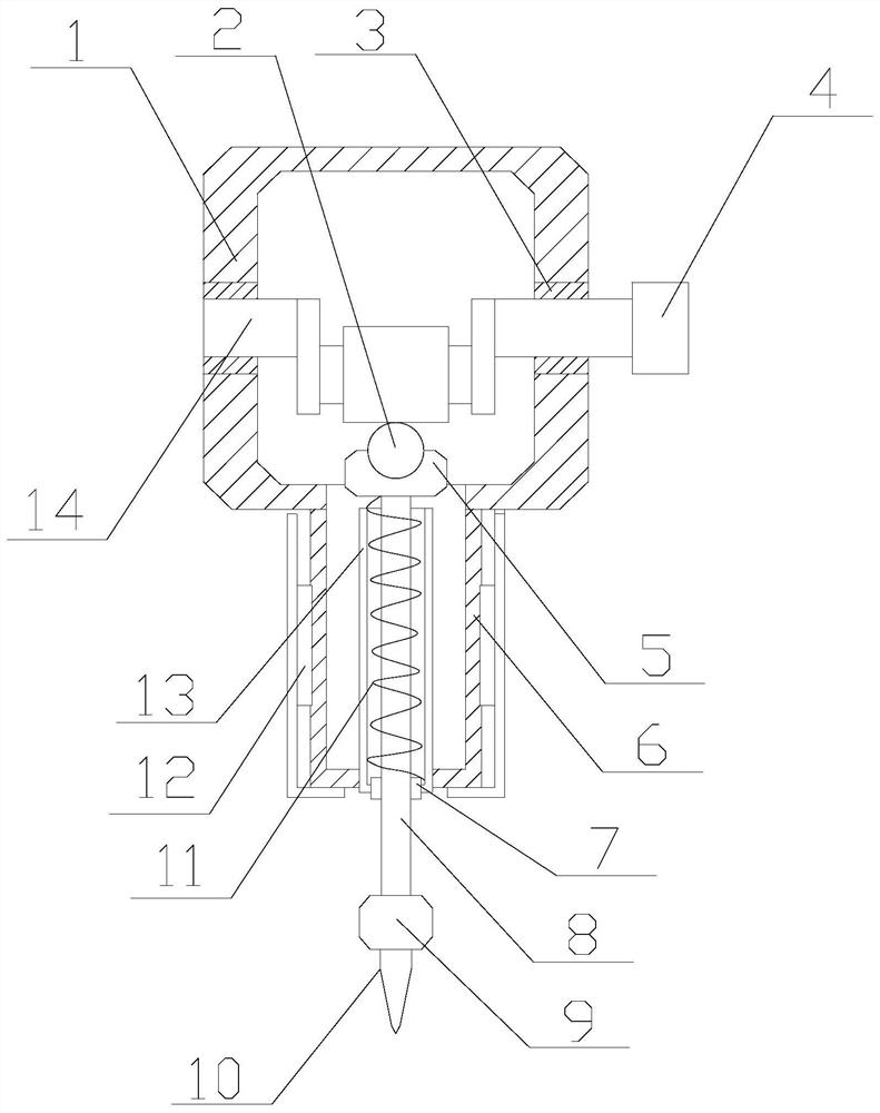
[0016] Such as figure 1 As shown, a cutting machine head assembly includes a housing, a driving device and a driven device; the housing includes a mounting seat 1 and a positioning seat 6, and the mounting seat 1 and the positioning seat 6 are provided with cavities inside, and the positioning seat 6 is fixedly placed on the bottom of the mounting seat 1, and the positioning seat 6 communicates with the mounting seat 1; the outer fixed sleeve of the positionin...


PUM


Abstract

The invention provides a machine head assembly of a cutting machine, belongs to the technical field of cutting machines, and aims at solving the problems that when a machine head of an existing cutting machine is used for cutting operation, the noise is high, the vibration amplitude of a tool bit is small, the cutting efficiency is low, and energy consumption is high. A transmission mode of a motor of the existing cutting machine is changed; a crankshaft is driven by the motor to move; a tool bit is driven by the crankshaft to do vertical reciprocating movement; the cutting amplitude is greater, and the efficiency is higher; the crankshaft is in point contact with a cutter bar, the friction force is small, and energy loss of cutting is effectively reduced; and reciprocating movement of the cutter bar is more stable, and the cutting noise is lower.

Description

technical field [0001] The invention relates to the technical field of cutting machines, in particular to a cutting machine head assembly. Background technique [0002] At present, as a common tool, cutting machines play an important role in the field of production and processing. When the existing cutting machine is performing cutting operations, the vibration distance of the cutter head is small, which reduces the effective range of cutting and reduces the cutting efficiency; increasing the motor transmission speed corresponds to increased noise and energy consumption, and the temperature of the motor itself rises, which easily causes damage to the cutting parts , greatly increasing the cost of use. Contents of the invention [0003] In view of the above-mentioned technical deficiencies, the purpose of the present invention is to provide a cutting machine head assembly. By changing the transmission mode of the existing cutting machine motor, the motor drives the cranksh...

Claims


Application Information

Patent Timeline
IPC IPC(8): B26D1/06B26D5/08B26D5/14
CPCB26D1/06B26D5/086B26D5/14
Inventor 郄利军
Owner 郄利军
Why Eureka
Try Eureka