Convenient wall perforating device for building construction

A technology of building construction and punching device, which is applied to work accessories, manufacturing tools, stone processing tools, etc., can solve problems such as long consumption time, unfavorable operator's health, hole punching stability, adaptive adjustment, safety defects, etc.

Pending Publication Date: 2021-07-06
JIANGSU SUZHONG CONSTR GROUP
View PDF0 Cites 0 Cited by
  • Summary
  • Abstract
  • Description
  • Claims
  • Application Information

AI Technical Summary

Problems solved by technology

[0002] At present, the domestic construction industry is developing rapidly, and people have higher and higher requirements for housing, not only housing demand, but also commercial demand, so the construction industry is in an era of rapid development, but some construction tools on the construction site are indeed very simple. As a result, a lot of manpower and material resources are consumed in the process of building construction, and the time consumed is also very long. Therefore, it is very necessary to upgrade the construction tools. The improvement of construction to

Method used


Image

  • Convenient wall perforating device for building construction
  • Convenient wall perforating device for building construction
  • Convenient wall perforating device for building construction

Examples


Embodiment 1

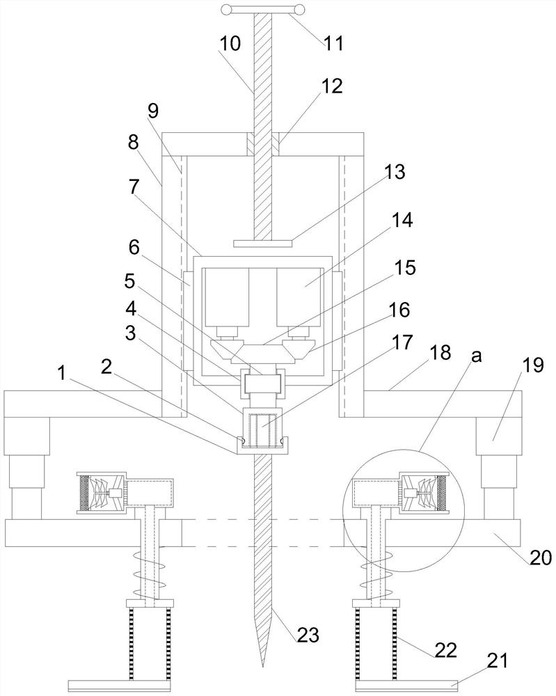
[0026] see Figure 1~3 , in an embodiment of the present invention, a convenient wall punching device for building construction, including a support mounting plate 18, one side of the support mounting plate 18 is facing with a displacement mounting plate 20, and the other side of the support mounting plate 18 is A support mounting cylinder 8 is vertically arranged, and the displacement mounting plate 20 facing the support mounting cylinder 8 is provided with a job installation hole, and the four corners of the support mounting plate 18 are vertically provided with an electric control telescopic column 19, and the other side of the electric control telescopic column 19 is vertically arranged. One end is all fixed on the displacement installation plate 20, the inside of the support installation cylinder 8 is provided with a guide installation cylinder 7, and the outside of the guide installation cylinder 7 is symmetrically provided with a guide conductive column 6, and the inner ...

Embodiment 2

[0030] On the basis of Embodiment 1, through the cooperation of the guiding conductive column 6 and the guiding conductive groove 9, the power supply is still stable when the guiding is displaced, and the return spring 24 is used to weaken the vibration of the device during the drilling process and reduce the feeling of fatigue , while pulling back the force to reset can protect the safety of the perforating drill bit 23 to a certain extent.


PUM


Abstract

The invention relates to the field of building construction, in particular to a convenient wall perforating device for building construction. The convenient wall perforating device comprises a supporting mounting plate, wherein a displacement mounting plate is arranged on one side of the supporting mounting plate in a right opposite manner, a supporting mounting cylinder is vertically arranged on the other side of the supporting mounting plate, an operation mounting hole is formed in the position, right opposite to the supporting mounting cylinder, of the displacement mounting plate, electric control telescopic columns are vertically arranged at the four corners of the supporting mounting plate, the other ends of the electric control telescopic columns are fixed to the displacement mounting plate, a limiting bearing sleeve is arranged on the side, right facing the displacement mounting cylinder, of a guide mounting cylinder, stable punching operation of the device is achieved through a guide displacement moving structure, under telescopic displacement adjustment, adaptive adjustment of drilling at different depths is achieved, operation vibration is weakened through elastic reset, the safety of a drill bit is protected, dust at an operation station is greatly reduced through active flow guide, and the view field and the health of operators are guaranteed.

Description

technical field [0001] The invention relates to the field of building construction, in particular to a convenient wall punching device for building construction. Background technique [0002] At present, the domestic construction industry is developing rapidly, and people have higher and higher requirements for housing, not only housing demand, but also commercial demand, so the construction industry is in an era of rapid development, but some construction tools on the construction site are indeed very simple. As a result, a lot of manpower and material resources are consumed in the process of building construction, and the time consumed is also very long. Therefore, it is very necessary to upgrade the construction tools. The improvement of construction tools is equal to the improvement of the construction progress. It is understood that The problem of adopting an electric drill in the process of drilling holes in the wall during building construction is that it brings many ...

Claims


Application Information

Patent Timeline
IPC IPC(8): B28D1/14B28D7/00
CPCB28D1/146B28D7/00
Inventor 杨俊钱群任志欣郭峰黄煜
Owner JIANGSU SUZHONG CONSTR GROUP
Why Eureka
Try Eureka