
Intelligent injection molding manipulator

A manipulator and intelligent technology, applied in manipulators, program-controlled manipulators, chucks, etc., can solve problems such as increasing the manufacturing cost of intelligent injection manipulators, reducing the work efficiency of intelligent injection manipulators, and increasing clamping control steps of intelligent injection manipulators.

Inactive Publication Date: 2021-07-06
苗继涛
View PDF0 Cites 1 Cited by
  • Summary
  • Abstract
  • Description
  • Claims
  • Application Information

AI Technical Summary

Problems solved by technology

The execution and drive system is mainly designed to complete the normal functions of the arm. The parts are driven by pneumatics or motors to achieve the function of picking up objects. However, the clamping and adsorption of the existing intelligent injection molding manipulator needs to be controlled by external pneumatic equipment. , which greatly increases the manufacturing cost of the intelligent injection molding manipulator, and at the same time increases the control steps of the intelligent injection molding manipulator clamping, reduces the working efficiency of the intelligent injection molding manipulator, and proposes an intelligent injection molding manipulator

Method used


Image

  • Intelligent injection molding manipulator
  • Intelligent injection molding manipulator
  • Intelligent injection molding manipulator

Examples


Embodiment Construction

[0029] The following description serves to disclose the present invention to enable those skilled in the art to carry out the present invention. The preferred embodiments described below are only examples, and those skilled in the art can devise other obvious variations.

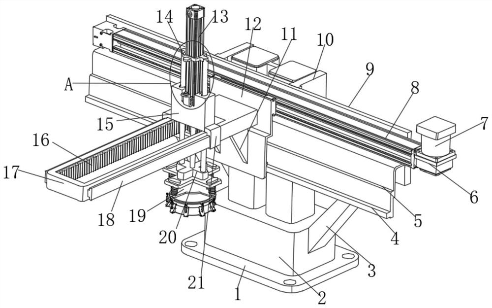
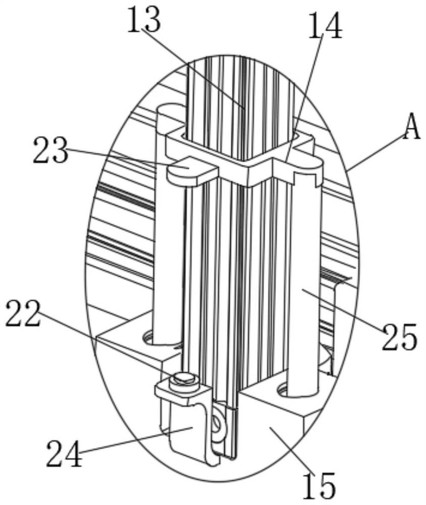
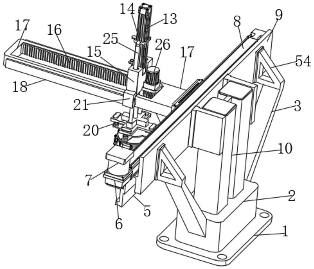
[0030] Such as Figure 1-Figure 9 A kind of intelligent injection molding manipulator shown, comprises rear frame plate 9, and the middle position of one side of rear frame plate 9 is provided with support mechanism, and support mechanism comprises the support frame 10 that is fixedly installed on the side middle position of rear frame plate 9, and support frame 10 The bottom end of the support seat 2 is fixedly installed with a support base 2, and the bottom end of the support base 2 is fixedly equipped with a fixed plate 1, and both ends of the support base 2 are obliquely connected with a reinforcing rod 3, and the top of the reinforcing rod 3 is connected to the side end of the rear frame plate 9. All a...


PUM


Abstract

The invention relates to the technical field of injection molding manipulators, in particular to an intelligent injection molding manipulator. The injection molding manipulator comprises a rear frame plate, a supporting mechanism is arranged in the middle of one side of the rear frame plate, a mounting plate is vertically arranged on the other side of the rear frame plate, the mounting plate and the rear frame plate are connected through a transverse driving mechanism, a fixing frame is horizontally connected to the side, away from the rear frame plate, of the mounting plate, two reinforcing plates are connected between one end of the bottom of the fixing frame and the mounting plate, dovetail sliding plates are horizontally connected to the two sides of the exterior of the fixing frame, sliding sleeves are slidably arranged on the outer sides of the dovetail sliding plates in a sleeving mode, a sliding base is fixedly mounted between the tops of the two sliding sleeves, a longitudinal driving mechanism is arranged between the sliding base and the fixing frame, and an adsorption clamping mechanism is arranged at the bottom of a cross-shaped bottom plate. The injection molding manipulator has an automatic suction and suction clamping function, and compared with the prior art, an air supply device is omitted, so that the manufacturing cost is greatly reduced, and meanwhile, the working efficiency is improved.

Description

technical field [0001] The invention relates to the field of injection molding manipulators, in particular to an intelligent injection molding manipulator. Background technique [0002] Injection molding manipulator is a machine specially equipped for injection molding production automation. It can reduce heavy physical labor, improve working conditions and safe production; it can imitate some functions of the upper limbs of the human body, and it can be automatically controlled to transport products according to predetermined requirements or Automated production equipment that handles tools for production operations. [0003] The manipulators applicable in the injection molding industry can be divided into the following two types according to their intelligence: 1. Basic injection manipulators; 2. Intelligent injection manipulators. The composition of intelligent injection molding manipulator is generally composed of execution system, drive system, control system and so on...

Claims


Application Information

Patent Timeline
Patent Type & Authority Applications(China)
IPC IPC(8): B29C45/42B25J9/00B25J9/02B25J9/10B25J9/12B25J15/06
CPCB25J9/0009B25J9/023B25J9/102B25J9/123B25J15/0616B29C45/4225B29C2045/4266
Inventor 苗继涛
Owner 苗继涛
Learn More