Portable fence for power maintenance and repair
A fence and power technology, applied in the direction of fences, building types, buildings, etc., can solve the problems of inconvenient disassembly and carrying, unfavorable power maintenance, and difficult position change of power fences.
- Summary
- Abstract
- Description
- Claims
- Application Information
AI Technical Summary
Problems solved by technology
Method used
Image

Examples
Embodiment 1
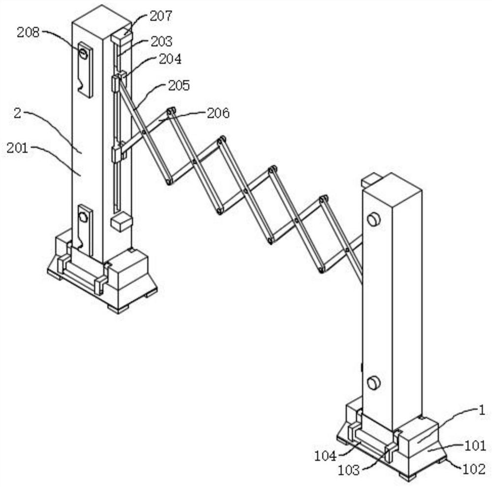
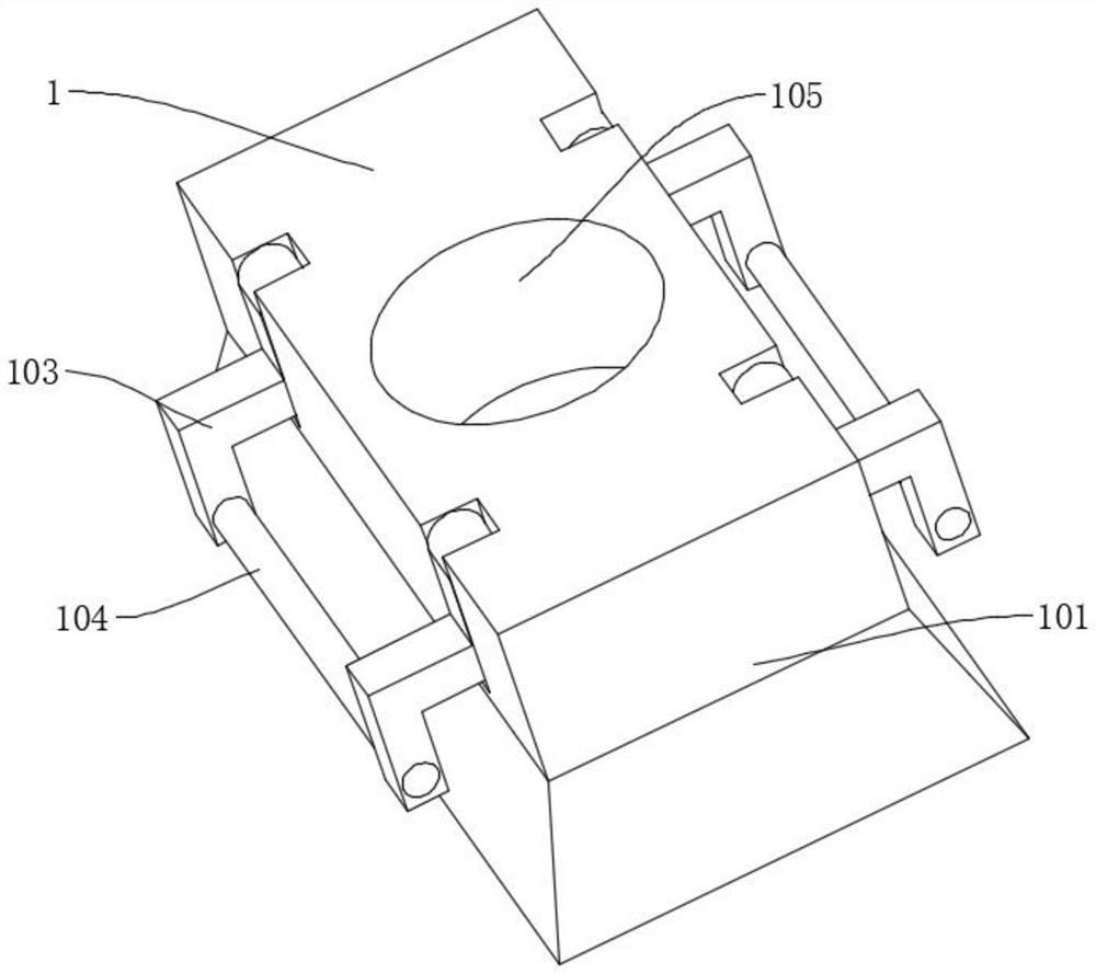
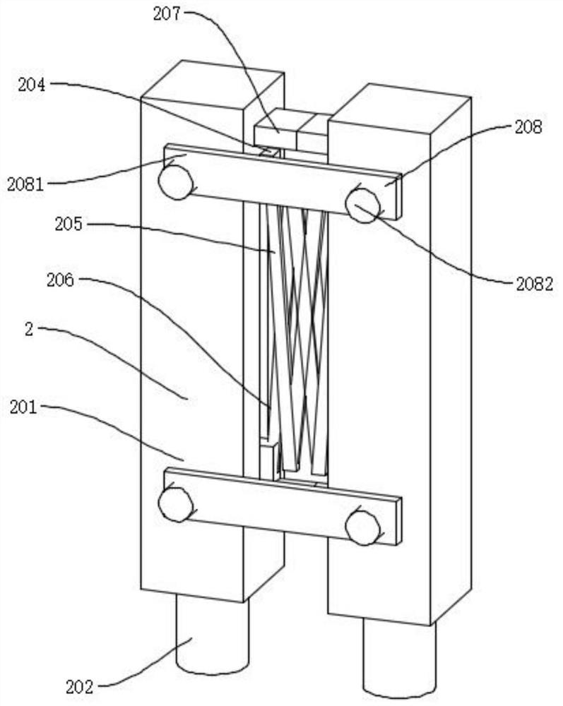
[0023] like figure 1 , figure 2 and image 3 As shown, the portable fence for electric maintenance and emergency repair includes a base 1 and a fence 2 inserted on the base 1. The base 1 includes a base body 101, a leg 102, a folding rod 103, a handle 104, a socket 105, and the base body The bottom of 101 is connected with supporting feet 102 by bolts, and the folding rods 103 are rotatably connected to both sides of the base body 101, and the handles 104 are rotatably connected between the folding rods 103, and the center of the base body 101 is provided with jacks 105 from top to bottom, so that Setting, the entire base 1 can be easily lifted through the handle 104, the outer side of the folding rod 103 is provided with a non-slip sleeve, and the fence 2 includes a column 201, an insertion rod 202, a chute 203, a slider 204, a first connecting rod 205, a second Connecting rod 206, buffer block 207, connecting mechanism 208, inserting rod 202 is integrally formed under the...
Embodiment 2
[0026] like Figure 4 As shown, the difference between Embodiment 2 and Embodiment 1 is that the connection mechanism 208 includes a tightening belt 20801, a clip joint 20802, a sun-shaped buckle 20803, and a clip seat 20804. The tightening strap 20801 is connected to the outside of the column 201 by screws. One end of the tightening belt 20801 bypasses the column 201 and the Japanese buckle 20803 on the other side, and is connected with a snap joint 20802, and the other end of the tightening band 20801 is connected with a snap socket 20804, and the snap joint 20802 is clipped and connected with the snap socket 20804, In this way, the length of the tightening belt 20801 can be adjusted through the Japanese-shaped buckle 20803, and the connection between the columns 201 can be made tighter by snapping the Japanese-shaped buckle 20803 into the clamping seat 20804.
[0027] In the above structure, when in use, first place the base 1 in a proper position, then remove the clip conn...
PUM
 Abstract
Description
Claims
Application Information
 - R&D Engineer
- R&D Manager
- IP Professional
- Industry Leading Data Capabilities
- Powerful AI technology
- Patent DNA Extraction
Browse by: Latest US Patents, China's latest patents, Technical Efficacy Thesaurus, Application Domain, Technology Topic.
© 2024 PatSnap. All rights reserved.Legal|Privacy policy|Modern Slavery Act Transparency Statement|Sitemap