

Fault moment prediction method for vibration monitoring of reactor shaft seal pump
A technology of fault time and vibration monitoring, applied in nuclear reactor monitoring, reactor, pump control, etc., can solve problems such as unpredictable measurement problems
- Summary
- Abstract
- Description
- Claims
- Application Information
AI Technical Summary
Problems solved by technology
Method used
Image

Examples
Embodiment 1
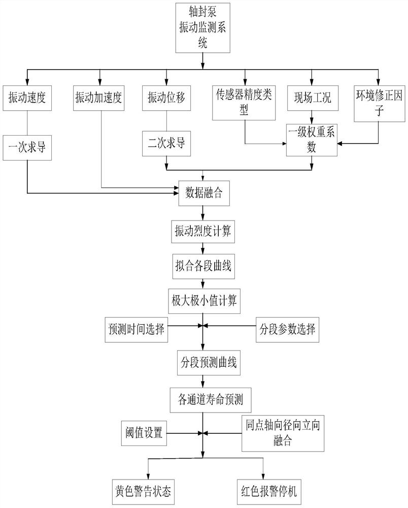
[0104] Such as figure 1 , figure 2 Shown:
[0105] A failure time prediction method for reactor shaft seal pump vibration monitoring,
[0106] A method for predicting failure time of reactor shaft seal pump vibration monitoring, comprising the following steps:
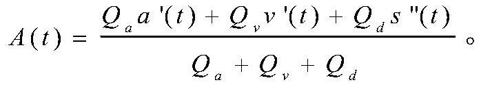
[0107] Step 1: Get the initial time T Init to the current time T now Under conditions, the monitoring data of the shaft seal pump of the reactor, the monitoring data include: vibration acceleration a(t), vibration velocity v(t), vibration displacement s(t), T now ≥t≥T Init ;
[0108] Step 2: Determine the first-level acceleration weight coefficient Q according to the sensor accuracy type of the vibration acceleration sensor, vibration speed sensor, and vibration displacement sensor, on-site working conditions, and environmental correction factors a , the first-level speed weight coefficient Q v , first-order displacement weight coefficient Q d ;;
[0109] Step 3: Put the vibration acceleration a(t), vibratio...
Embodiment 2
[0123] Such as figure 1 , figure 2 Shown:
[0124] A preferred further scheme is as follows: the method of determining the final predicted fault time at the predicted time includes: it can be directly adopted; it is also possible to perform multiple high-order nonlinear function fitting processes to obtain multiple predicted curves in order to improve the accuracy and obtain multiple intersection points, The time of final prediction of failure is determined after calculation of arithmetic accuracy improvement at multiple prediction times; among them, since there may be multiple effective curve segments within a measurement time range, it is also possible to improve the current The general process is to obtain the final predicted fault time corresponding to multiple effective curve segments according to the above method for a single effective curve segment, and then fuse the above-mentioned final predicted fault time to obtain the final predicted fault time time.
[0125] S...
Embodiment 3
[0175] On the basis of above-mentioned embodiment 1 and 2,
[0176] Specifically, the method of determining the effective curve segment is as follows: the specific process of step 5 is as follows:
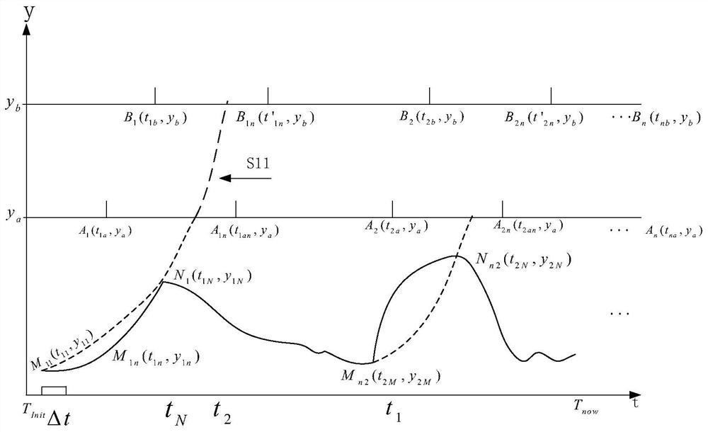
[0177] Deriving the fitted curve to obtain minimum and maximum values, marking the fitted curve with minimum and maximum values to obtain multiple curve segments;
[0178] From the multiple curve segments, the rising edge curve segment is screened out, and the rising edge curve segment is an effective curve segment for predicting the fault moment;
[0179] Among them, the rising edge curve segment is: taking the time as the abscissa, along the direction of the abscissa, the curve segment where the minimum value first appears and then the maximum value appears.
[0180] Specifically, the specific way of preprocessing the monitoring data is: the specific process of step 3 is:
[0181] Firstly, the vibration acceleration a(t) is directly obtained a'(t), the vibration velocity v(t)...
PUM
 Abstract
Description
Claims
Application Information