Error detection device for machining
An error detection and machining technology, applied in the field of error detection devices for machining, can solve the problems of large error in vernier caliper measurement, slow detection and measurement efficiency, inaccurate measurement data, etc.
- Summary
- Abstract
- Description
- Claims
- Application Information
AI Technical Summary
Problems solved by technology
Method used
Image
Examples
Embodiment 1
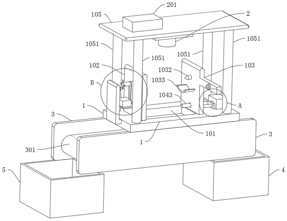
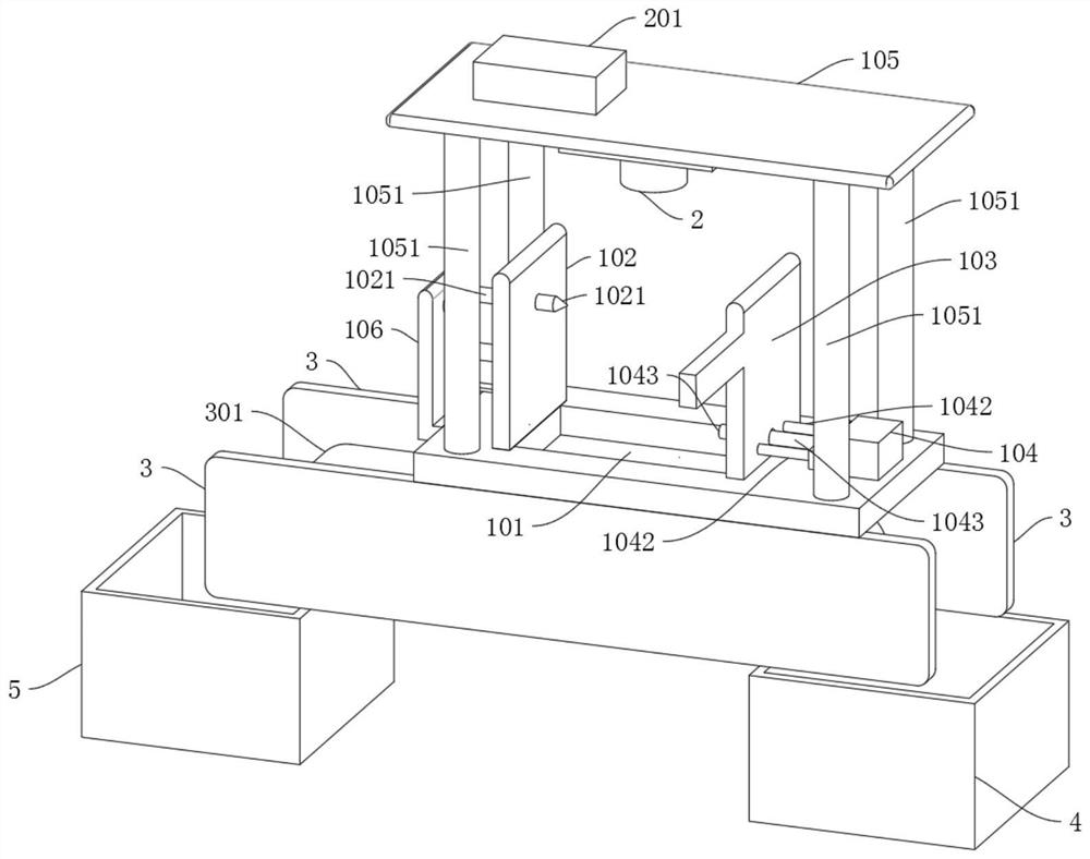
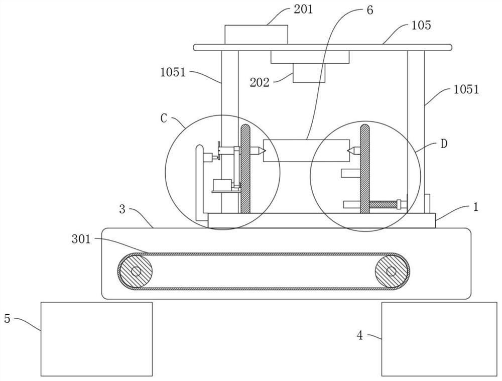
[0029] refer to Figure 1-7 , an error detection device for machining, comprising a lower fixing plate 1, an upper fixing plate 105, and a cylindrical body 6, and also includes: a first mounting plate 102, a second mounting plate 103, and fastening bolts are fixed on the lower fixing plate 1; The first positioning shaft 1021 is rotatably connected to the first mounting plate 102; the servo motor 1022 is connected to the first positioning shaft 1021; the second positioning shaft 1032 is rotatably connected to the second mounting plate 103; the driving assembly is connected to the lower fixing plate 1, used to drive the second mounting plate 103 to move; the image collector 2, fastening bolts fixed on the upper fixing plate 105, used for image acquisition of the cylindrical body 6; the trigger assembly, connected to the lower fixing plate 1, used To trigger the image collector 2 to take pictures; the data processing system 201 is electrically connected to the image collector 2, ...
Embodiment 2
[0036] refer to Figure 1-7 , an error detection device for machining, which is basically the same as in Embodiment 1, furthermore: the drive assembly includes a small motor 104, a fixed block 1041, and a guide post 1042, and the small motor 104 is fastened to the lower fixed plate 1 with fastening bolts, The output end of small motor 104 is welded with threaded rod 1043, and fixed block 1041 is screwed and connected on the threaded rod 1043, and guide post 1042 is welded on the fixed block 1041 symmetrically, and two groups of guide posts 1042 are welded on the second end away from fixed block 1041. On the mounting plate 103, the small motor 104 is electrically connected to the data processing system 201;
[0037] After the start signal is transmitted to the small motor 104 by the data processing system 201, the small motor 104 works to drive the threaded rod 1043 to rotate, the fixed block 1041 moves on the threaded rod 1043 to the direction close to the first mounting plate...
Embodiment 3
[0039] refer to Figure 1-7 , an error detection device for machining, which is basically the same as that of Embodiment 1, furthermore: the trigger assembly includes a trigger block 1024, a sensor body 1061, a side fixing plate 106 is welded on the lower fixing plate 1, and the side fixing plate 106 is located at On one side of the first mounting plate 102, the sensor body 1061 is glued to the side fixing plate 106, the first positioning shaft 1021 runs through the first mounting plate 102, and the end of the first positioning shaft 1021 away from the first mounting plate 102 is welded with four A group of trigger blocks 1024, four groups of trigger blocks 1024 are evenly distributed on the first positioning shaft 1021, the trigger block 1024 is matched with the sensor body 1061, and the sensor body 1061 is electrically connected with the data processing system 201;
[0040] The servo motor 1022 works, drives the first positioning shaft 1021 to rotate through the belt 1023, a...
PUM
 Abstract
Description
Claims
Application Information
 - R&D
- Intellectual Property
- Life Sciences
- Materials
- Tech Scout
- Unparalleled Data Quality
- Higher Quality Content
- 60% Fewer Hallucinations
Browse by: Latest US Patents, China's latest patents, Technical Efficacy Thesaurus, Application Domain, Technology Topic, Popular Technical Reports.
© 2025 PatSnap. All rights reserved.Legal|Privacy policy|Modern Slavery Act Transparency Statement|Sitemap|About US| Contact US: help@patsnap.com


