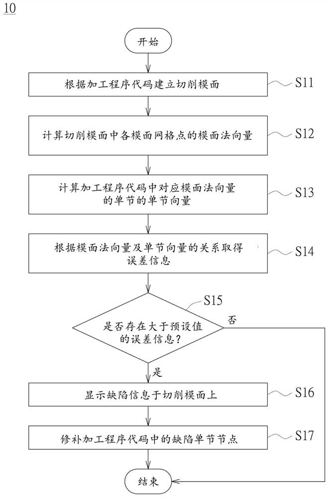
Method for inspecting defects of machining path
A defect detection and processing path technology, applied in image data processing, instruments, 3D modeling, etc., can solve the problem that the processing path is difficult to observe with the naked eye.
- Summary
- Abstract
- Description
- Claims
- Application Information
AI Technical Summary
Problems solved by technology
Method used
Image

Examples
Embodiment Construction
[0036] Various embodiments of the present invention will be described in detail below and illustrated with accompanying drawings. In addition to these detailed descriptions, the present invention can also be widely implemented in other embodiments, and any easy substitution, modification, and equivalent change of any of the described embodiments are included in the scope of the present invention, and with the appended rights Requirements prevail. In the description of the specification, many specific details and implementation examples are provided in order to enable readers to have a more complete understanding of the present invention; however, these specific details and implementation examples should not be regarded as limitations of the present invention. Also, well-known steps or elements have not been described in detail in order to avoid unnecessarily limiting the invention. It should be noted that the drawings are only for illustration and convenience of description, ...
PUM
 Abstract
Description
Claims
Application Information
 - R&D Engineer
- R&D Manager
- IP Professional
- Industry Leading Data Capabilities
- Powerful AI technology
- Patent DNA Extraction
Browse by: Latest US Patents, China's latest patents, Technical Efficacy Thesaurus, Application Domain, Technology Topic.
© 2024 PatSnap. All rights reserved.Legal|Privacy policy|Modern Slavery Act Transparency Statement|Sitemap