Battery cell, battery and electric equipment
A cell and electrode assembly technology, applied in the field of battery manufacturing, can solve problems such as cell short circuit
- Summary
- Abstract
- Description
- Claims
- Application Information
AI Technical Summary
Problems solved by technology
Method used
Image

Examples
no. 1 example
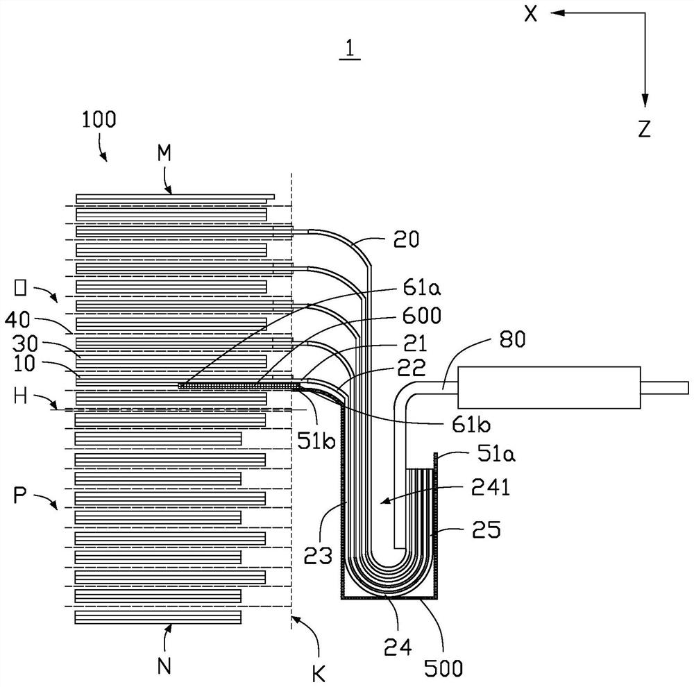
[0068] see figure 1 , the present application provides an electric core 1, the electric core 1 includes an electrode assembly 100 and a first insulating member 500, and the first insulating member 500 is arranged on the electrode assembly 100 for separating the electrode assembly 100 , to avoid the short circuit of the battery cell 1 during the manufacturing process of the battery cell 1 .
[0069] The overall outer surface of the electrode assembly 100 includes a first surface M, a first end surface K and a second surface N formed in sequence. Wherein, the first surface M and the second surface N are two opposite surfaces of the electrode assembly 100, and the first end surface K is formed between the first surface M and the second surface N , and the first end face K is perpendicular to the first surface M and the second surface N respectively.
[0070] The electrode assembly 100 includes a first pole piece 10 and a first pole lug 20 , one end of the first pole piece 20 is...
no. 2 example
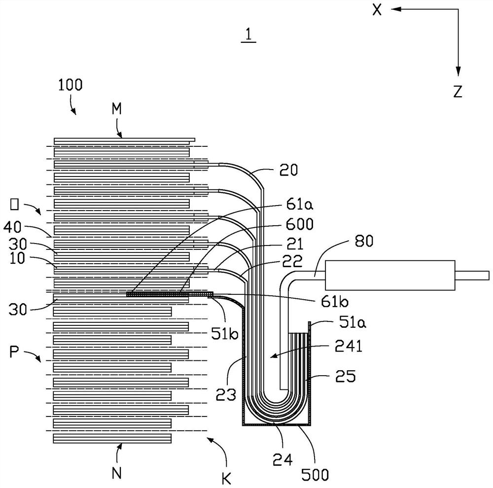
[0094] see figure 2 The structure of the cell 1 provided in the second embodiment of the present application is substantially the same as that of the cell 1 in the first embodiment, the difference is that the surface of the first end 61a of the second insulator 600 is pasted on the first part O is the outermost surface of the second pole piece 30, and the other surface of the first end 61a of the second insulating member 600 is pasted on the outermost surface of the diaphragm 40 of the second part P. Wherein, the outermost second pole piece 30 of the first part O refers to the second pole piece 30 closest to the second part P in the first part O. The outermost membrane 40 surface of the second part P refers to the membrane 40 closest to the first part O in the second part P.
[0095] The structure of the cell 1 is the same as that in the first embodiment, the second end 61b of the second insulating member 600 is connected to the second end 51b of the first insulating member ...
no. 3 example
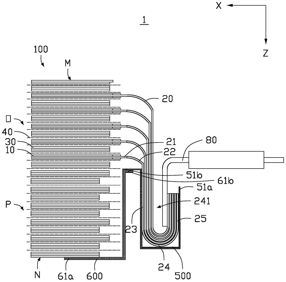
[0098] see image 3 The structure of the cell 1 provided by the third embodiment of the present application is substantially the same as that of the cell 1 in the first embodiment, the difference is that, along the first direction Z, the first end 61a of the second insulating member 600 Extending to the second surface N and sticking on the second surface N. The structure of the cell 1 is the same as that in the first embodiment, the second end 61b of the second insulating member 600 is connected to the second end 51b of the first insulating member 500 .
[0099] Specifically, the first end 51a of the first insulator 500 starts from the surface of the third straight section 25, extends around the second bent portion 24, and surrounds the second bent portion. The portion 24 faces away from the surface of the groove 241 . The first insulating member 500 continues to extend along the second straight section 23 and is disposed on the surface of the second straight section 23 unti...
PUM
 Abstract
Description
Claims
Application Information
 - R&D
- Intellectual Property
- Life Sciences
- Materials
- Tech Scout
- Unparalleled Data Quality
- Higher Quality Content
- 60% Fewer Hallucinations
Browse by: Latest US Patents, China's latest patents, Technical Efficacy Thesaurus, Application Domain, Technology Topic, Popular Technical Reports.
© 2025 PatSnap. All rights reserved.Legal|Privacy policy|Modern Slavery Act Transparency Statement|Sitemap|About US| Contact US: help@patsnap.com