Roll core assembly structure and method

An assembly structure and assembly method technology, which is applied in the field of lithium-ion batteries, can solve the problems of dust easily entering the winding core, large tabs, and increased manufacturing costs, so as to avoid the risk of battery short circuit, reduce gaps, and increase energy density. Effect

Active Publication Date: 2021-04-23
HEFEI GUOXUAN HIGH TECH POWER ENERGY
View PDF11 Cites 4 Cited by
  • Summary
  • Abstract
  • Description
  • Claims
  • Application Information

AI Technical Summary

Problems solved by technology

[0003] 1) During the pre-welding and final welding of the tabs of the winding core, dust will inevitably be generated, and the dust will easily enter the inside of the winding core;
[0004] 2) When the winding core is put into the shell, it is easy to scratch between the aluminum shell and cause a short circuit of the battery;
[0005] 3) The above assembly method needs to reserve a long tab for core assembly, which increases the manufacturing cost;
[0006] 4) After welding, the lug is subjected to a large force due to bending, and it is prone to the risk of breaking due to pulling;
[0007] 5) After the tab is bent, it is located between the cover plate and the winding core of the aluminum shell. The bent tab prevents close contact between the cover plate and the battery core, resulting in a large gap between the cover plate and the winding core. Limits the improvement of battery energy density;
[0008] 6) The above assembly method is currently applicable to the assembly of double winding cores, and cannot adapt to the parallel assembly of more winding cores

Method used


Image

  • Roll core assembly structure and method
  • Roll core assembly structure and method
  • Roll core assembly structure and method

Examples


Embodiment Construction

[0060] The technical solutions of the present invention will be described in detail below in conjunction with the accompanying drawings and specific embodiments. It should be understood that these embodiments are only used to illustrate the present invention and not to limit the scope. After reading the present invention, those skilled in the art will understand the present invention Modifications of various equivalent forms fall within the scope defined in the present application.

[0061] It should be noted that when an element is referred to as being “disposed on” another element, it may be directly on the other element or there may also be an intervening element. When an element is referred to as being "connected to" another element, it can be directly connected to the other element or intervening elements may also be present. As used herein, the terms "vertical", "horizontal", "upper", "lower", "left", "right" and similar expressions are for the purpose of illustration on...


PUM

PropertyMeasurementUnit
lengthaaaaaaaaaa

Abstract

The invention provides a roll core assembly structure and method. The roll core assembly structure and method are used for assembling a roll core, and the roll core comprises a roll core body and a tab extending from the roll core body. The assembly structure comprises: a partition plate assembly comprising a partition plate body, wherein the partition plate body comprises a top wall and at least one side wall, the top wall and the side walls define a containing part used for containing the roll core body, and the partition plate assembly further comprises a connecting piece arranged on the top wall and having conductivity; and a cover plate assembly including a substrate having a first surface and a second surface, a conducting strip arranged on the first surface and used for being connected with the connecting strip, and a pole arranged on the second surface, wherein the pole is electrically conducted with the conducting strip. According to the specification, the manufacturing qualification rate can be improved, and multi-roll core assembly can be carried out.

Description

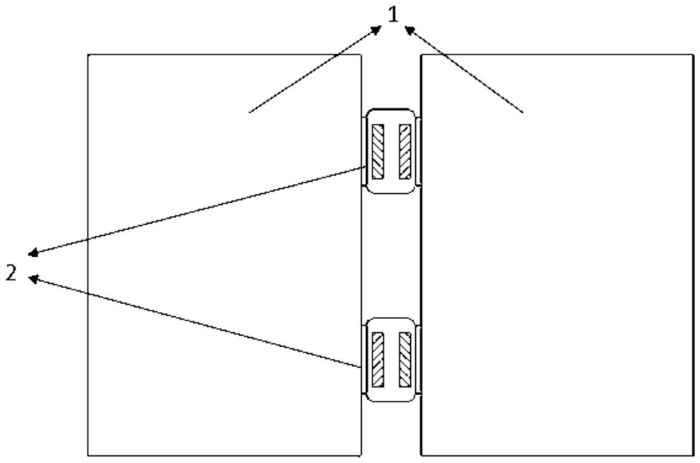
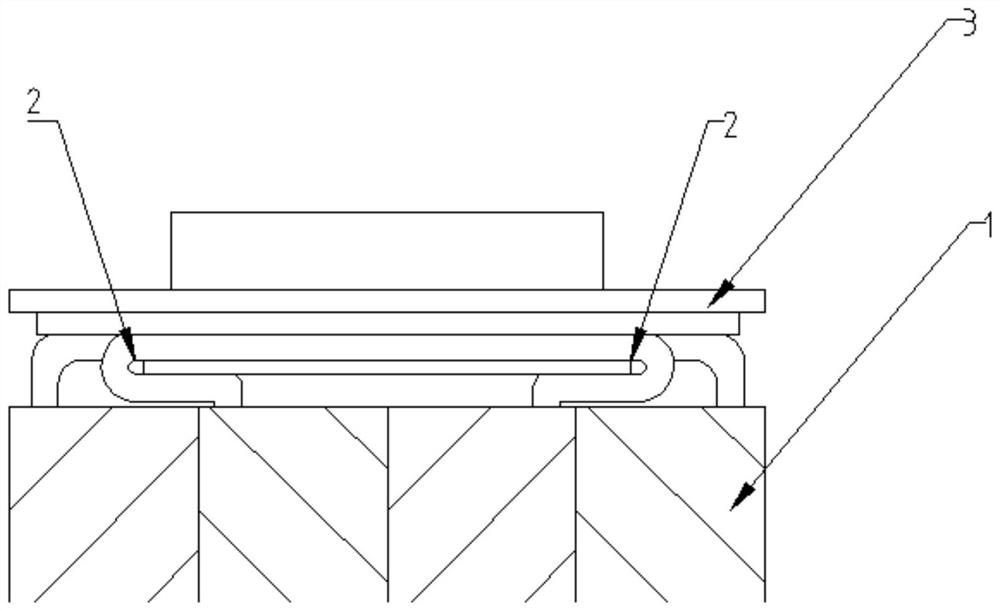
technical field [0001] The present application relates to the technical field of lithium-ion batteries, in particular to a winding core assembly structure and assembly method. Background technique [0002] At present, the winding core assembly of power lithium batteries mostly adopts the "butterfly welding" method. Take the assembly of two winding cores as an example, such as figure 1 As shown, first pre-solder the tabs 2 of the core 1, and then face the tabs 2 of the two cores 1, and place the tabs 2 between the connecting sheet and the small protective sheet, and then connect the The tabs, the tabs 2 and the small protective sheet are welded together, so that the tabs 2 of the two winding cores 1 are connected as one. Subsequently, if figure 2 As shown, bend the connecting part of the tab 2, put the winding core 1 into the shell, and install the cover plate 3 above the tab 2 to complete the assembly. However, there are still certain defects in this assembly method, ma...

Claims


Application Information

Patent Timeline
Patent Type & Authority Applications(China)
IPC IPC(8): H01M50/10H01M50/147H01M50/50H01M50/531H01M10/0587H01M10/0525
CPCH01M10/0587H01M10/0525Y02E60/10Y02P70/50
Inventor 高冲
Owner HEFEI GUOXUAN HIGH TECH POWER ENERGY
Why Eureka
Try Eureka