Movable display stand for architectural design

An architectural design and display stand technology, applied in display stands, display hangers, display shelves, etc., can solve the problems of poor display effect and inconvenience, so as to improve the display effect and facilitate observation and learning.

Inactive Publication Date: 2021-07-09
INNER MONGOLIA UNIV OF TECH
View PDF0 Cites 0 Cited by
  • Summary
  • Abstract
  • Description
  • Claims
  • Application Information

AI Technical Summary

Problems solved by technology

[0003] At present, it is necessary to use a display stand to display samples in the architectural design process, but in the prior art, when the display stand displays samples, the display height and display angle of the samples are fixed, the display effect is poor, and it is not convenient for people to use. Therefore, in view of the above status quo, it is urgent to develop a mobile display stand for architectural design to overcome the deficiencies in current practical applications.

Method used


Image

  • Movable display stand for architectural design
  • Movable display stand for architectural design
  • Movable display stand for architectural design

Examples


Embodiment 1

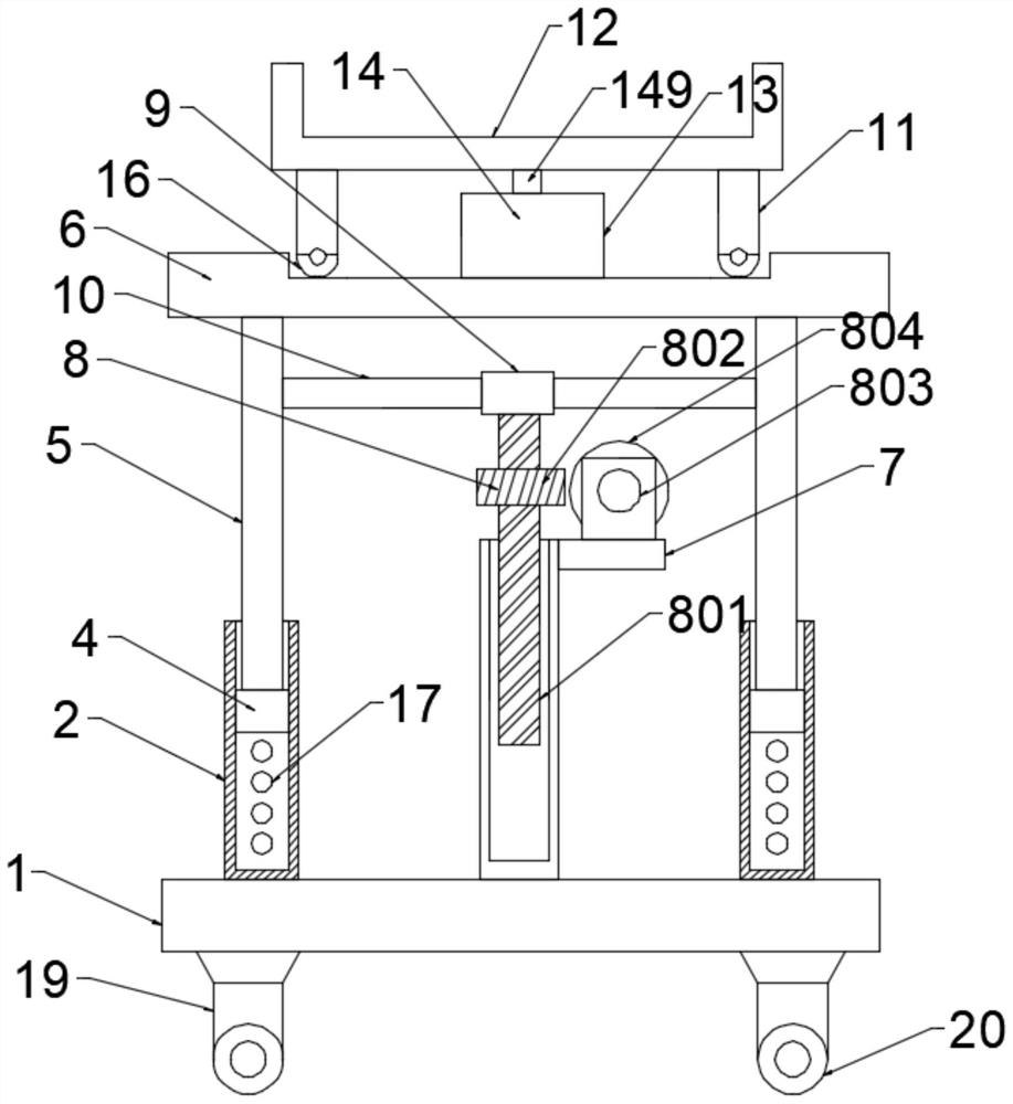
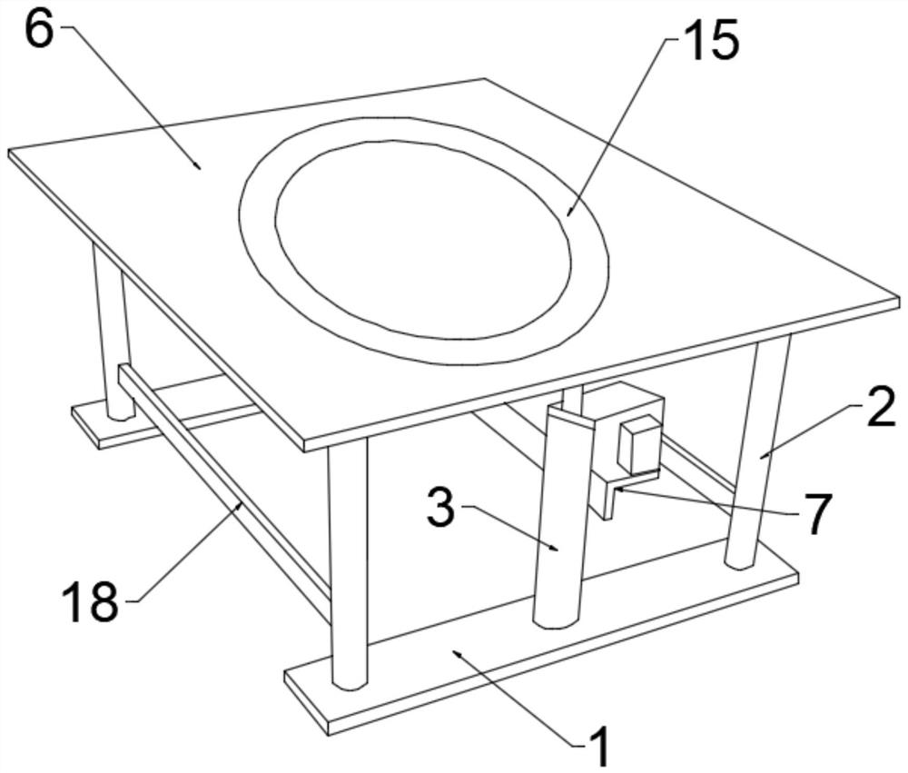
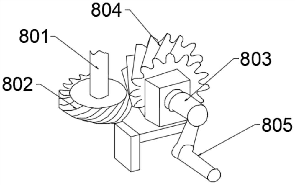
[0025] see Figure 1-5 , in an embodiment of the present invention, an architectural design mobile display stand includes a base plate 1, two base plates 1 are arranged symmetrically with each other, and support columns 2 are symmetrically fixedly connected to the left and right ends of the top end of the base plate 1, two A threaded sleeve 3 is installed in the middle of the support column 2, a support rod 5 is slidably connected to the inside of the support column 2, and a display plate 6 is fixedly connected to the top ends of the two support rods 5, and a top end of the threaded sleeve 3 has a The side is fixedly connected with a mounting frame 7, and the top of the mounting frame 7 is fixedly provided with a lifting device 8, and the lifting device 8 includes a threaded rod 801. The threaded rod 801 is threaded inside the threaded sleeve 3, and the top is fixedly connected with a Fixed block 9, the left and right ends of described fixed block 9 are horizontally connected ...

Embodiment 2

[0032] see Figure 1-5 , in this embodiment, the rotating device 14 includes a rotating block 140, the rotating block 140 is provided with two and fixedly connected with the inner bottom wall and the top wall of the dustproof frame 13 respectively, and the inside is connected with a rotating shaft through a rotating shaft. Disk 141, the middle of the top of the rotating disk 141 is fixed with a rotating plate 142, the upper surface of the rotating plate 142 is provided with a plurality of groups of symmetrical arc-shaped chute 143, one of the arc-shaped chute 143 is internally connected with a circular Rotating block 144, one end of the circular rotating block 144 is fixedly connected with a rotating rod 145, one end of the rotating rod 145 is fixedly connected with a drive rod 146 outward, and the outer edge of the rotating plate 142 is fixedly connected with a positioning rod through a connecting plate 147, the rotation center of the rotating plate 142 is fixedly connected w...


PUM


Abstract

The invention relates to the technical field of building design, in particular to a building design movable display stand which comprises two bottom plates, the two bottom plates are symmetrically arranged, supporting columns are symmetrically and fixedly connected to the left and right ends of the top ends of the bottom plates, a threaded sleeve is installed between the two supporting columns, and supporting rods are slidably connected into the supporting columns. A display panel is fixedly connected to the top ends of the two supporting rods, a mounting frame is fixedly connected to one side of the top end of the threaded sleeve, a lifting device is fixedly arranged at the top end of the mounting frame and comprises a threaded rod, the threaded rod is in threaded connection with the interior of the threaded sleeve, and a fixing block is fixedly connected to the top end of the threaded rod; the left end and the right end of the fixing block are transversely connected with connecting rods, and the ends, away from the fixing block, of the connecting rods are fixedly connected with the supporting rod. By arranging the lifting device and the rotating device, the display height and the display angle of the bearing plate can be effectively adjusted, so that the display effect of the bearing plate is improved, and people can use the bearing plate conveniently.

Description

technical field [0001] The invention relates to the technical field of architectural design, in particular to a mobile display stand for architectural design. Background technique [0002] Architectural design means that before the construction of a building, the designer, according to the construction task, makes a comprehensive assumption in advance of the problems that exist or may occur during the construction process and use process, and draws up the methods and plans to solve these problems. Drawings and documents express it. The product model in the architectural design needs the help of a display stand to facilitate the comprehensive display of the architectural design content. [0003] At present, it is necessary to use a display stand to display samples in the architectural design process, but in the prior art, when the display stand displays samples, the display height and display angle of the samples are fixed, the display effect is poor, and it is not convenien...

Claims


Application Information

Patent Timeline
Patent Type & Authority Applications(China)
IPC IPC(8): A47F5/10A47F5/025A47F7/00A47F11/00
CPCA47F5/025A47F5/10A47F7/00A47F11/00
Inventor 郝占国苏晓明王磊
Owner INNER MONGOLIA UNIV OF TECH
Why Eureka
Try Eureka