
Thin-wall box clamp mechanism

A thin-walled box and fixture technology, used in clamping, manufacturing tools, metal processing machinery parts, etc., can solve the problems of poor pin hole position, complicated operation, shell deformation, etc., and meet the requirements of convenient assembly, labor saving, and coordination. Not high, to ensure the effect of deformation

Active Publication Date: 2021-07-09
XUZHOU XCMG DRIVELINE TECH CO LTD
View PDF6 Cites 3 Cited by
  • Summary
  • Abstract
  • Description
  • Claims
  • Application Information

AI Technical Summary

Problems solved by technology

[0002] In the process of mechanical processing, various kinds of shell processing are often encountered. The shell processing requirements are high, and the shell inner hole, end face and end face pin hole are high. For ordinary shells, the traditional fixture structure can It meets the processing requirements, but the operation is complicated and the efficiency is low. For a certain thin-walled shell, it cannot meet the processing requirements. The shell deformation is serious, resulting in out-of-tolerance coaxiality and out-of-tolerance pin hole position

Method used


Image

  • Thin-wall box clamp mechanism
  • Thin-wall box clamp mechanism
  • Thin-wall box clamp mechanism

Examples


Embodiment Construction

[0045] The implementation of the technical solution will be further described in detail below in conjunction with the accompanying drawings. The following examples are only used to illustrate the technical solution of the present invention more clearly, but not to limit the protection scope of the present invention.

[0046] In the description of the present invention, it should be noted that the terms "upper", "lower", "front", "rear", "left", "right", "vertical", "inner", "outer" etc. The indicated orientation or positional relationship is based on the orientation or positional relationship shown in the drawings, and is only for the convenience of describing the present invention and simplifying the description, rather than indicating or implying that the referred device or element must have a specific orientation, or in a specific orientation. construction and operation, therefore, should not be construed as limiting the invention.

[0047] In the description of the presen...


PUM


Abstract

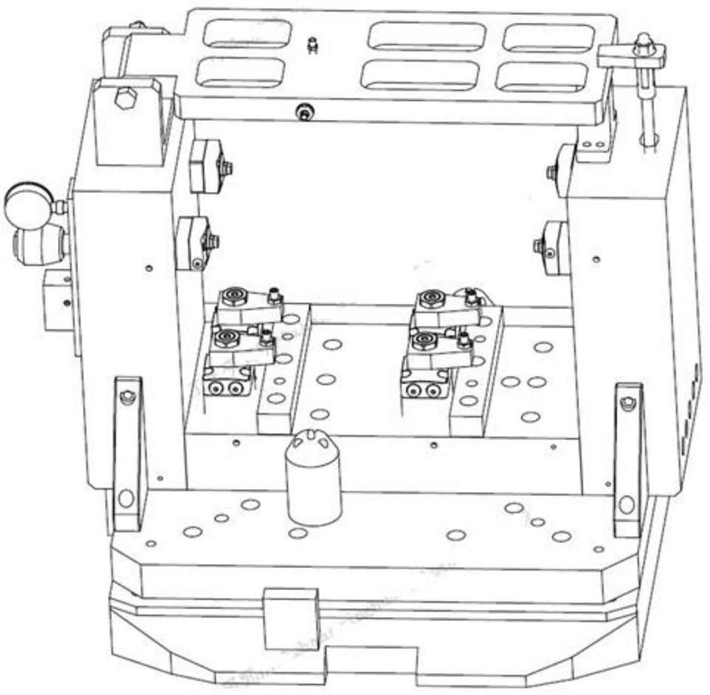
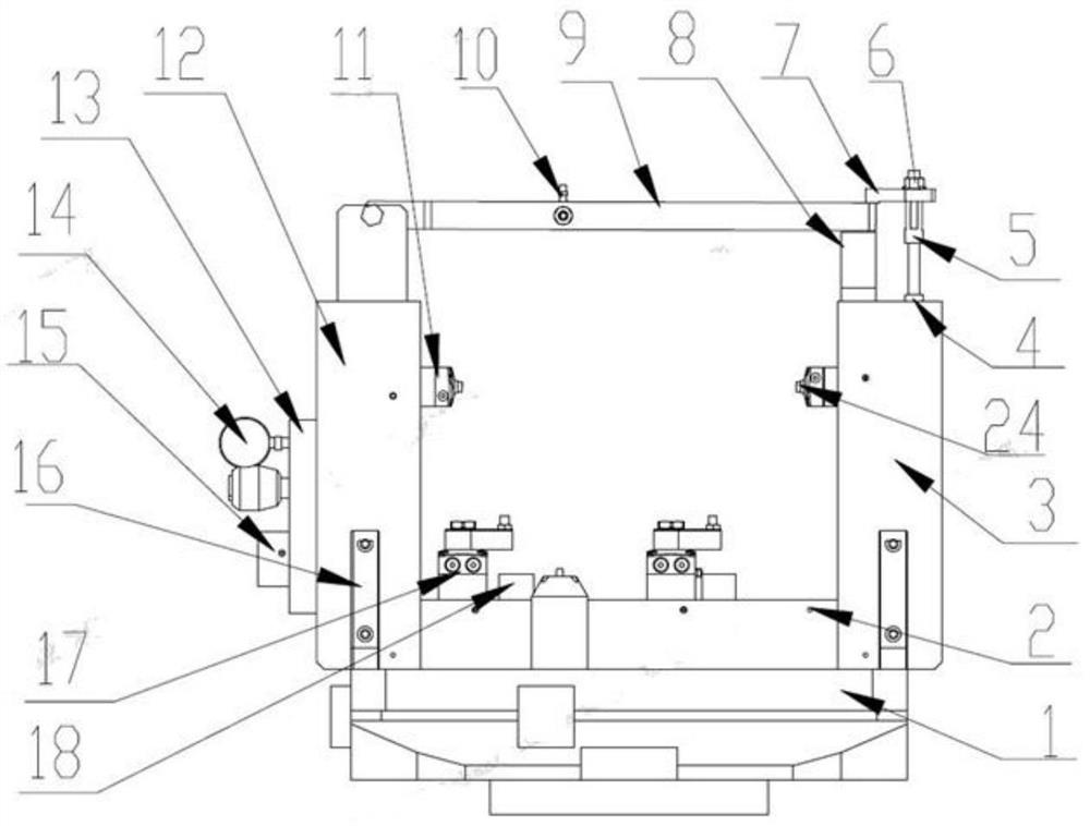
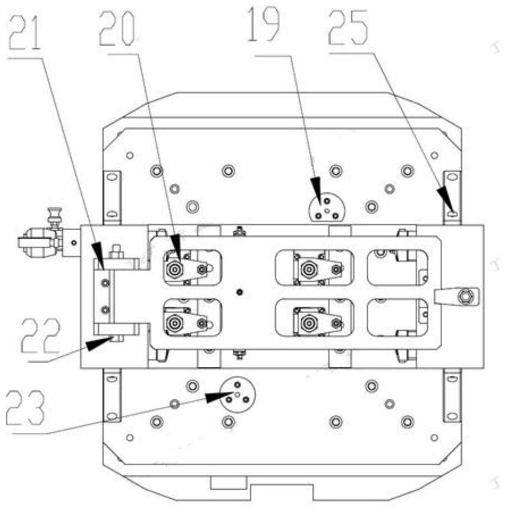
The invention discloses a thin-wall box clamp mechanism which comprises a base assembly, a positioning mechanism, a hydraulic fixing mechanism and a pressing mechanism; the base assembly comprises a positioning plate, a left side plate and a right side plate which are connected in a U shape, and the inner side of the base assembly is used for containing a workpiece; the positioning mechanism is mounted on the upper side of the base assembly and is used for positioning the workpiece; the hydraulic fixing mechanism is arranged on the inner side of the base assembly; the pressing mechanism is mounted on the upper sides of the left side plate and the right side plate and connected with the left side plate and the right side plate; and the positioning mechanism, the hydraulic fixing mechanism and the pressing mechanism make contact with the periphery of the workpiece correspondingly, and multi-point pressing is conducted on the workpiece. The thin-wall box clamp mechanism adopts an ingenious mechanical structure, the mechanism is simple in structure, low in matching requirement, convenient for machining, low in cost and convenient and labor-saving in assembling, in the workpiece clamping process, one-face two-pin positioning and hydraulic clamping are achieved, pressing force is adjusted through pressure, and deformation of a workpiece in the machining process is avoided.

Description

technical field [0001] The invention discloses a thin-walled box clamp mechanism, which relates to the technical field of mechanical processing. Background technique [0002] In the process of mechanical processing, various kinds of shell processing are often encountered. The shell processing requirements are high, and the shell inner hole, end face and end face pin holes are high. For ordinary shells, the traditional fixture structure can It meets the processing requirements, but the operation is complicated and the efficiency is low. For a certain thin-walled shell, it cannot meet the processing requirements, and the shell deformation is serious, resulting in out-of-tolerance coaxiality and out-of-tolerance pin hole position. Contents of the invention [0003] The present invention aims at the defects in the above-mentioned background technology, and provides a thin-walled box clamp mechanism, which is supported and pressed by multiple points, so as to eliminate various ...

Claims


Application Information

Patent Timeline
Patent Type & Authority Applications(China)
IPC IPC(8): B23Q3/08
CPCB23Q3/082Y02E60/10
Inventor 张英华马淑侠叶春红丁文涛
Owner XUZHOU XCMG DRIVELINE TECH CO LTD
Learn More