Floating body structure for ocean engineering

A technology for marine engineering and structures, applied in special purpose ships, ships, ship safety and other directions, can solve problems such as damaged maintenance, difficulties, losses, etc., to achieve the effect of stable structure and function and improve performance stability

Inactive Publication Date: 2021-07-09
曹太平
View PDF0 Cites 0 Cited by
  • Summary
  • Abstract
  • Description
  • Claims
  • Application Information

AI Technical Summary

Problems solved by technology

[0003] The environment in the ocean is complex, and extreme environments often occur. For example, strong winds and waves will overturn the floating body structure. If the overturned floating body structure cannot be corrected in time, it may cause damage and bring difficulties to future maintenance. , thus causing losses. After exploration by our R&D personnel, we now provide a new overturning automatic overturning and rectification scheme applicable to offshore floating structures and large-scale offshore buoyant platforms in the future. Due to the extreme situation that the internal sensors and other components of the offshore floating body structure fail due to the harsh environment, the present invention provides a solution to avoid the use of sensitive electronic equipment such as sensors to the greatest extent, and improve the stability of the mechanism during operation through the mechanical structure

Method used


Image

  • Floating body structure for ocean engineering
  • Floating body structure for ocean engineering
  • Floating body structure for ocean engineering

Examples


Embodiment Construction

[0030] The following will clearly and completely describe the technical solutions in the embodiments of the present invention with reference to the accompanying drawings in the embodiments of the present invention. Obviously, the described embodiments are only some, not all, embodiments of the present invention. Based on the embodiments of the present invention, all other embodiments obtained by persons of ordinary skill in the art without making creative efforts belong to the protection scope of the present invention.

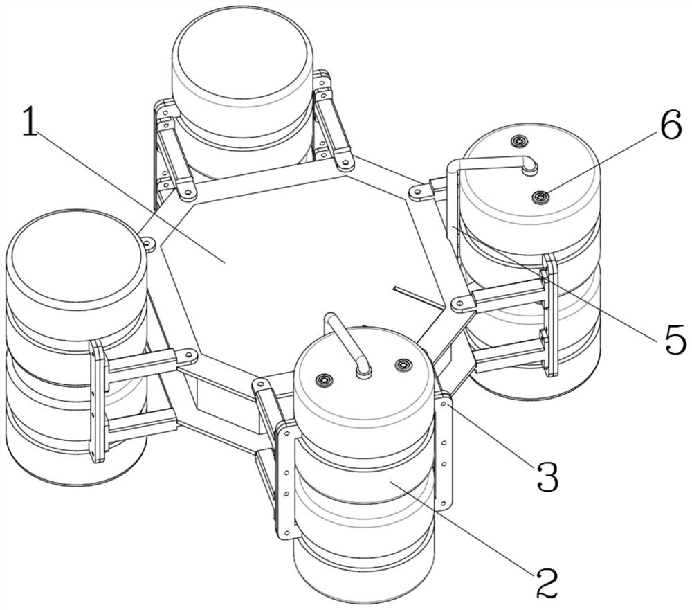
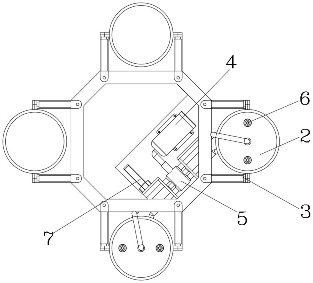
[0031] Such as Figure 1 to Figure 10 As shown, in the embodiment of the present invention, a floating body structure for marine engineering includes an equipment box 1, a buoy 2 and an installation frame 3, the buoy 2 is fixedly installed with the equipment box 1 through the installation frame 3, and the buoys 2 are arranged together There are eight and two groups are divided into four groups. The two groups of buoys 2 located on the right side of the equipme...


PUM


Abstract

The invention belongs to the technical field of ocean engineering, and discloses a floating body structure for ocean engineering. The floating body structure comprises an equipment box, floating buckets and a mounting rack; the floating buckets are fixedly mounted on the equipment box through the mounting rack; the number of the floating buckets is eight, and the floating buckets are divided into four groups each of which comprises two two floating buckets; the two groups of floating buckets positioned on the right side of the equipment box are numbered as No.3 and No.4; and a compressed air tank, an air flow dividing and guiding device and a deflection switch are arranged in an inner cavity of the equipment box. According to the floating body structure of the invention, pressure valves are additionally arranged on the No.1 floating bucket and the No.2 floating bucket, the No.1 floating bucket and the No.2 floating bucket can be automatically submerged into water after being overturned, the whole floating body structure forms a vertical posture; air is injected into the second floating bucket firstly according to the automatic position condition of the first floating bucket filled with water relative to the position condition of the second floating bucket, and the floating body structure deflects towards the second floating bucket; when the trend in the deflection direction is irreversible, the buoyancy is increased for the main body of the No.1 floating bucket, and finally the whole floating body structure is overturned and corrected again to keep a correct posture.

Description

technical field [0001] The invention belongs to the technical field of marine engineering, and in particular relates to a floating body structure for marine engineering. Background technique [0002] Floating body structures are used in marine engineering for ocean exploration, detection and navigation, and even the main bearing platform of future offshore wind power stations. The main function of floating body structures is to provide strong buoyancy by themselves, so that their carrying equipment can float on the water. , to complete functions such as surveying and navigation, and it also has unit equipment that can generate electricity according to ocean waves to provide power for its own modules. [0003] The environment in the ocean is complex, and extreme environments often occur. For example, strong winds and waves will overturn the floating body structure. If the overturned floating body structure cannot be corrected in time, it may cause damage and bring difficultie...

Claims


Application Information

Patent Timeline
Patent Type & Authority Applications(China)
IPC IPC(8): B63B35/00B63B43/12
CPCB63B35/00B63B43/12B63B2043/126
Inventor 不公告发明人
Owner 曹太平
Why Eureka
Try Eureka