Elastic supporting mechanism, optical component driving mechanism, image pick-up device and electronic equipment
A technology of elastic support and shrapnel, which is applied in the direction of optical components, optics, installation, etc., can solve the problems of increased cost, large posture difference, inconsistent shaking of double shrapnel, etc., to ensure camera accuracy and stability, improve driving accuracy, and shrink The effect of poor posture
Pending Publication Date: 2021-07-09
NEW SHICOH MOTOR CO LTD
0 Cites 0 Cited by
AI-Extracted Technical Summary
Problems solved by technology
[0003] The existing periscope motor generally adopts a double-carrier structure, which carries an optical prism. The optical prism has an incident optical axis and an outgoing optical axis. There are two types of shrapnel used to drive the X-axis and Y-axis between the carrier and the base. Different shrapnels are connected separately, whi...
Method used
At the bottom of the hole of the Y-axis mounting hole 414, a Y-axis glue storage tank 414b is provided, and the inner connection block 61a is fixed in the Y-axis installation hole 414 by being filled in the glue in the Y-axis glue storage groove 414b. Meanwhile, the Y-axis The driving magnet 6a and the inner connection block 61a are fixed by glue connection or the like. Except for the position of the orientation protrusion 60a, the circumferential side of the Y-axis drive magnet 6a is flush with the circumferential side of the inner connecting block 61a, so as to facilitate installation and fixation.
Based on the above-mentioned structure of this base 2, the X-axis electromagnetic drive corresponding to the inclined distribution of the circuit inclined part 32, and then cooperate with the Y-axis electromagnetic drive, which can make the prism L0 have X-axis and Y when adjusting the offset when driving The axis is rotated and adjusted at the same time, which greatly improves the efficiency of adjusting the offset, and further improves the accuracy and reliability of the prism drive.
On the basis of above-mentioned embodiment two, as shown in Figure 17, the present invention also provides a kind of imaging device, has the optical component driving mechanism L described in above-mentioned embodiment two, and lens driving mechanism T, lens driving The mechanism T is located at the light exit port 101. The optical component driving mechanism L is used to change the optical path, and the lens driving mechanism T cooperates to realize high-precision ultra-clear imaging.
Preferably, the light exit port 101 of the present embodiment is arranged on one of the two opposite long-circumferential sides of the casing 10, the long-circumferential side is the front side, and this design can optimize the overall structure layout, so that the overall structure of the housing installed with the optical component driving mechanism is more compact and reasonable.
That is to say, the corresponding protrusion 214 on the optical component driving mechanism can stretch into the functional hole 102 and match with the functional hole 102. At this time, the optical component driving mechanism is pre-positioned, and the subsequent post-processing During the process, limited by the functional hole 102, the optical component driving mechanism will not be displaced, which solves the problems of low assembly efficiency, poor quality, and high scrap rate.
The two shrapnels 5 are distributed along the optical axis direction of the optical component, preferably, the two shrapnels 5 are on the same longitudinal plane along the incident optical axis RS direction, the longitudinal plane and the incident optical axis The optical axes RS are distributed at intervals, or the incident optical axis RS is located on the longitudinal plane, and the position of the shrapnel can be set according to the actual position of the center of gravity. The two shrapnels 5 are distributed symmetrically with respect to the incident optical axis RS. To play the role of symmetrical elastic support.
Two side end bearing parts 21 are connected on the middle bearing part 20 and distributed at intervals, and the two side end bearing parts 21 are respectively used to fix the circuit side part 31 connected with the circuit middle part 30; preferably, two The side end bearing parts 21 are respectively connected to the two lengthwise ends of the middle bearing part 20, and the side end bearing parts 21 and the middle bearing part 20 are vertically connected. This structure is convenient for processing and manufacturing, and at the same time, the overall structural strength is very good.
Utilize the circuit inclined part 32 that is provided with inclination, it can make the X-axis coil 6c that is arranged on the circuit inclined part 32 combine the X-axis driving magnet 6d to realize that the single carrier 4 rotates around the X axis, not only improving the driving efficiency, but also The final camera accuracy is also improved.
Utilize two shrapnels 5 that are arranged along the incident optical axis RS direction, the X-axis electromagnetic drive mechanism of cooperative tilting type and the Y-axis electromagnetic drive mechanism, can realize the biaxial position rotation adjustment to single carrier 4, and biaxial is X Axis and Y axis, and make the posture difference of X/Y axis direction very small. At the same time, X/Y axis share the carrier, which can effectively solve the problem of FRA (shaking).
[0056] As shown in FIG. 5, the circuit board 3 includes a middle circuit portion 30, and a reinforcing member is embedded in the middle region of the middle circuit portion 30, so as to improve the structural strength of the middle portion 30 of the circuit.
[0068] The above-mentioned pin holes cooperate with the pins on the base 2 to achieve accurate positioning of the circuit board 3.
[0070] In a preferred solution, there are two U-shaped connecting parts 35 in this embodiment and they are distributed at intervals. to improve structural strength.
[0079] Secondly, the inclined bearing portion 22 is located between the two side end bearing portions 21. Preferably, the inclined bearing part 22 is located in the center between the two side end bearing parts 21, so as to ensure stable driving. Of course, the inclined bearing part 22 can be located at any position between the two side end bearing parts 21, furthermore, the number of inclined bearing parts 22 can also be two, and each inclined bearing part 22 is respectively arranged with a circuit inclined part 32 With the corresponding X-axis electromagnetic drive, the X-axis coil is connected in parallel to further increase the driving speed.
[0080] In the central area of the inclined bearing portion 22, an X-axis coil avoidance through hole 223 is provided. The X-axis coil 6c is installed on the circuit inclined part 32, and the X-axis coil 6c is placed in the X-axis coil escape hole 223, so as to prevent movement interference and improve disassembly efficiency.
[0081] The inclined surface 220 is provided with a first glue storage tank 221 and a first positioning pin 222. The first glue storage tank 221 is used to fix the inclined circuit portion 32 , and a first pin hole 320 for inserting the first positioning pin 222 is provided on the inclined circuit portion 32 , so as to realize stable fixing.
[0082] On the outer surface of each side end bearing portion 21, a concave positioning groove 210 is respectively provided, and the concave positioning groove 210 is used to fix the above-mentioned circuit side portion 31. The bottom of the concave positioning groove 210 is provided with a second positioning pin 211 and a second glue storage tank 212 . Similarly, the glue in the second glue storage tank 212 can enhance the connection strength with the circuit side 31, the circuit side 31 is provided with a second pin hole 310, and the second positioning pin 211 is inserted into the second pin hole, which can realize Securely fixed.
[0083] Secondly, Y-axis coil avoidance through holes 213 communicated with corresponding concave positioning grooves 210 are respectively provided on each side end bearing portion 21 . Improve th...
Abstract
The invention relates to an elastic supporting mechanism, an optical component driving mechanism, an image pick-up device device and electronic equipment. The defects of large posture difference, large size and the like in the existing X/Y-axis direction are overcome. The elastic supporting mechanism comprises: a single carrier located in the base; two elastic piece containing spaces, wherein one elastic piece containing space is located between one end of the Y axis of the single carrier and one end of the Y axis of the base, and the other elastic piece containing space is located between the other end of the Y axis of the single carrier and the other end of the Y axis of the base; elastic pieces, wherein the number of the elastic pieces is two, one elastic piece is arranged in one elastic piece containing space and is connected with the single carrier and the base respectively, and the other elastic piece is arranged in the other elastic piece containing space and is connected with the single carrier and the base respectively, and the two elastic pieces are positioned on the same longitudinal surface along the direction of the incident optical axis. The elastic supporting mechanism has the advantages that the posture difference in the X/Y-axis direction is reduced and the size is small.
Application Domain
Mountings
Technology Topic
EngineeringOptical axis +2
Image
Examples
- Experimental program(4)
Example Embodiment
[0054] Embodiment one
[0055] like Figure 9 and Figure 10 As shown, the base 2 is used to fix the circuit board 3 and carry a single carrier 4 .
[0056] like Figure 5 As shown, the circuit board 3 includes a middle circuit portion 30 , and reinforcing members are embedded in the middle region of the middle circuit portion 30 so as to improve the structural strength of the middle circuit portion 30 .
[0057] One end of the circuit board 3 is connected with a power terminal 33 for easy connection with a power source.
[0058] like Figure 5 and Figure 12-13 As shown, there are two circuit side portions 31 and they are distributed oppositely. The circuit side portion 31 is connected to the circuit middle portion 30 and is used for electrical connection with the Y-axis coil 6b.
[0059] The circuit slope portion 32 is located between the two circuit side portions 31 and slopes above the circuit middle portion 30 . The circuit inclined portion 32 is used to electrically connect the inclined X-axis coil 6c.
[0060] The middle part 30 of the circuit and the inclined part 32 of the circuit are distributed at an included angle of 45°, of course, other acute angles may also be used.
[0061] One of the circuit side portions 31 is connected to an end of the circuit middle portion 30 away from the electrical terminal 33 , and the other circuit side portion 31 is connected to the rear side of the circuit middle portion 30 through a bent portion 34 . The bent portion 34 here includes a rearward hanging part connected to the rear side of the circuit middle part 30, a vertical part connected to the free end of the backward hanging part and vertically connected to the rearward hanging part, and the above-mentioned circuit side part 31 is connected on the vertical department.
[0062] Utilize the inclined circuit portion 32, it can make the X-axis coil 6c arranged on the circuit inclined portion 32 combined with the X-axis driving magnet 6d realize the rotation of the single carrier 4 around the X-axis, which not only improves the driving efficiency, but also improves the Ultimate camera accuracy.
[0063] The circuit side portion 31 connected to the circuit middle portion 30 through the bent portion 34 is suspended above the circuit middle portion 30 .
[0064]There are several first pin holes 320 distributed on the upper side of the circuit inclined portion 32 , that is, the upper side of the inclined surface.
[0065] A second pin hole 310 is provided on the circuit side portion 31;
[0066] A third pin hole 300 is provided on the middle part 30 of the circuit;
[0067] And a fourth pin hole 340 is provided on the bending portion 34 .
[0068] The above-mentioned pin holes cooperate with the pins on the base 2 to realize accurate positioning of the circuit board 3 .
[0069] In addition, the circuit intermediate portion 30 and the circuit inclined portion 32 are connected by a U-shaped connection portion 35 . Further, a step groove 350 is provided on the upper surface of the connection between the U-shaped connecting portion 35 and the middle circuit portion 30, and the thickness of the U-shaped connecting portion 35 is smaller than the thickness of the middle portion 30 of the circuit and the U-shaped connecting portion 35 extends backward to The upper surface of the portion of the stepped groove and the U-shaped connecting portion 35 and the stepped groove distributed at intervals and the U-shaped connecting portion 35 protruding into the stepped groove does not exceed the upper surface of the circuit middle portion 30 . This structure is designed mainly for the convenience of installing the circuit board 3 .
[0070] Preferably, there are two U-shaped connecting parts 35 in this embodiment and they are distributed at intervals. to improve structural strength.
[0071] Preferably, the two circuit side portions 31 of this embodiment are parallel to each other, and the circuit inclined portion 32 is located in the middle between the two circuit side portions 31 .
[0072] The structure of base 2 is described in detail as follows:
[0073] like Figure 6-8 As shown, the base 2 includes an intermediate bearing portion 20 for fixing the intermediate circuit portion 30 of the circuit board 3; the intermediate bearing portion 20 is in the shape of a rectangular block.
[0074] Two side end bearing parts 21 are connected to the middle bearing part 20 and distributed at intervals, and the two side end bearing parts 21 are respectively used to fix the circuit side part 31 connected with the circuit middle part 30; preferably, the two side end bearing parts The parts 21 are respectively connected to the two longitudinal ends of the middle bearing part 20, and the side end bearing parts 21 and the middle bearing part 20 are vertically connected. This structure is convenient for processing and manufacturing, and at the same time, the overall structural strength is very good.
[0075] The two circuit side parts 31 are corresponding to Y-axis electromagnetic drive and the two side end bearing parts 21 are oppositely distributed.
[0076] The inclined surface 220 is disposed on the intermediate carrying portion 20 and is used for fixing the circuit inclined portion 32 connected to the intermediate carrying portion 20 .
[0077] Based on the above-mentioned structure of the base 2, the circuit inclined part 32 corresponds to the X-axis electromagnetic drive of the inclined distribution, and then coordinates the Y-axis electromagnetic drive, which can make the prism L0 rotate simultaneously with the X-axis and the Y-axis when the offset is adjusted. The adjustment greatly improves the efficiency of adjusting the offset, and further improves the accuracy and reliability of the prism drive.
[0078] In a preferred solution, an inclined bearing portion 22 is provided at the central area of the intermediate bearing portion 20 in this embodiment, and the rear side surface of the inclined bearing portion 22 is the aforementioned inclined surface 220 . The design of the inclined bearing part 22 can form a triangular reinforcement to the structure of the structural base 2 , and at the same time, can also be used to fix the inclined part 32 of the circuit.
[0079] Secondly, the inclined bearing part 22 is located between the two side end bearing parts 21 . Preferably, the inclined bearing part 22 is located in the center between the two side end bearing parts 21, so as to ensure stable driving. Of course, the inclined bearing part 22 can be located at any position between the two side end bearing parts 21, furthermore, the number of inclined bearing parts 22 can also be two, and each inclined bearing part 22 is respectively arranged with a circuit inclined part 32 With the corresponding X-axis electromagnetic drive, the X-axis coil is connected in parallel to further increase the driving speed.
[0080] An X-axis coil avoidance through hole 223 is provided in the central area of the inclined bearing portion 22 . The X-axis coil 6c is installed on the circuit inclined part 32, and the X-axis coil 6c is placed in the X-axis coil escape hole 223, so as to prevent movement interference and improve disassembly efficiency.
[0081] A first glue storage tank 221 and a first positioning pin 222 are provided on the inclined surface 220 . The first glue storage tank 221 is used to fix the inclined circuit portion 32 , and a first pin hole 320 for inserting the first positioning pin 222 is provided on the inclined circuit portion 32 , so as to realize stable fixing.
[0082] A concave positioning groove 210 is respectively provided on the outer surface of each side end bearing portion 21 , and the concave positioning groove 210 is used for fixing the above-mentioned circuit side portion 31 . The bottom of the concave positioning groove 210 is provided with a second positioning pin 211 and a second glue storage tank 212 . Similarly, the glue in the second glue storage tank 212 can enhance the connection strength with the circuit side 31, the circuit side 31 is provided with a second pin hole 310, and the second positioning pin 211 is inserted into the second pin hole, which can realize Securely fixed.
[0083] Secondly, a Y-axis coil avoidance through hole 213 communicating with the corresponding concave positioning groove 210 is respectively provided on each side end bearing portion 21 . Improve the efficiency of disassembly and assembly, and play an avoidance role.
[0084] In addition, a bottom positioning groove 200 communicating with the two concave positioning grooves 210 is provided at the bottom of the intermediate carrying portion 20 , and the bottom positioning groove 200 is used for fixing the middle portion 30 of the circuit. In this way, it can facilitate the installation of the circuit board 3 and protect the circuit board 3 from contacting the housing 1 at the connecting corner of the bottom positioning groove 200 and the concave positioning groove 210 to cause wear and damage. The upper surface of the part of the above-mentioned U-shaped connecting portion 35 extending into the stepped groove does not exceed the upper surface of the middle circuit portion 30, which can prevent the middle portion 30 of the circuit from protruding from the lower surface of the middle bearing portion 20, so as to prevent The contact on circuit board 3 is damaged.
[0085] Two escape notches 203 are provided on the bottom front side of the intermediate bearing part 20 for the U-shaped connecting part 35 to extend into, and the avoidance notches communicate with the bottom positioning groove 200 .
[0086] Similarly, if Figure 6-7 As shown, a third positioning pin 201 and a third glue storage tank 202 are provided at the bottom of the bottom positioning groove 200 . That is, the glue in the third glue storage tank 202 improves the fixing fastness with the middle part 30 of the circuit, and at the same time, a third pin hole is provided on the middle part 30 of the circuit, so as to facilitate the insertion and positioning of the third positioning pin 201 .
[0087] In addition, the rear support portion 23 is connected to the rear side of the middle bearing portion 20, the upper side of the inclined bearing portion 22 is connected to the rear support portion 23, and the rear side of the side end bearing portion 21 is connected to the rear support portion 23. The supporting part 20 , the rear supporting part 23 , the inclined supporting part 22 and the side end supporting part 21 enclose a single carrier accommodating space, and the single carrier 4 is installed in the single carrier accommodating space through an elastic supporting mechanism.
[0088] There are two shrapnel accommodation spaces between the single carrier 4 and the base 2, one shrapnel 5 accommodation space is located between one end of the Y axis of the single carrier and one end of the Y axis of the base, and the other shrapnel 5 accommodation space is located at the other end of the Y axis of the single carrier and the other end of the Y axis of the base;
[0089] Further, a fourth glue storage tank 230 is provided on the rear surface and/or top of the rear support portion 23 . A fifth glue storage tank 215 is disposed on the top and/or outer surface of the side end bearing portion 21 . The glue in the fourth glue storage tank 230 and the fifth glue storage tank 215 can improve the connection strength with the shell 1 and prevent falling off.
[0090] like Figure 1-4 As shown, the base 2 is installed in the shell 1 , in order to improve the assembly efficiency of the shell 1 and the base 2 and prevent mutual displacement, a protruding portion 214 is respectively connected to the front side of each side end bearing portion 21 .
[0091] Specifically, the above-mentioned casing 1 includes a housing 10, inside of which there is a cavity for accommodating the driving mechanism of the optical components;
[0092] The casing 10 is made of metal material, such as sheet metal material, etc., which has very good rigidity, so as to play the role of protection, support and fixation. Of course, non-metallic materials can also be used in this embodiment as long as they can meet the above requirements.
[0093] The light entrance 100 is arranged on the top side of the casing 10 and communicates with the cavity;
[0094] The light exit port 101 is arranged in the circumferential direction of the casing 10 and communicates with the light entry port 100, and the light exit port 101 communicates with the cavity;
[0095] Preferably, the light entrance 100 of this embodiment is a U-shaped opening, and the light exit 101 is also a U-shaped opening, and the two are connected to facilitate the manufacturing of the housing and the disassembly and assembly of the final prism.
[0096] The functional hole 102 is disposed on the housing 10 and is used to limit the displacement of the optical component driving mechanism relative to the housing 10 . The shape of the functional hole 102 is any one or a combination of oval holes, square holes, triangular holes and T-shaped holes. Of course, it can also be other special-shaped holes. This embodiment does not give excessive examples of the shape of the functional holes. .
[0097] That is to say, the corresponding protrusion 214 on the optical component driving mechanism can extend into the functional hole 102 and match the functional hole 102. At this time, the optical component driving mechanism is pre-positioned, and in the subsequent post-processing process, Limited by the functional hole 102, the optical component driving mechanism will not be displaced, which solves the problems of low assembly efficiency, poor quality, and high scrap rate.
[0098] Preferably, there are two functional holes 102 in this embodiment and they are distributed on both sides of the light exit port 101 . The two functional holes 102 can provide positioning on a horizontal plane, which prevents the same displacement phenomenon due to the design of a single hole, especially a single circular hole, that is, when a circular hole is selected, the number of circular holes is designed to be two.
[0099] It is arranged on both sides to facilitate the installation of the optical component driving mechanism, so as to improve the assembly efficiency.
[0100] Preferably, the housing 10 of this embodiment is in a rectangular shape, of course, it can also be in other shapes such as a square. The rectangular structure can reduce the overall volume as much as possible, so as to be applied to various camera devices, for example, mobile phones and the like.
[0101] In a preferred solution, the light exit 101 of this embodiment is arranged on one of the two relatively long peripheral sides in the circumferential direction of the casing 10, and the long peripheral side is the front side. This design can optimize the layout of the entire structure, so as to This makes the overall structure of the casing installed with the optical component driving mechanism more compact and reasonable.
[0102] Secondly, one of the functional holes 102 is provided on the long peripheral side, and the other functional hole 102 is provided at the corner of the long peripheral side and the short peripheral side adjacent to the long peripheral side. The above distribution method can make the overall structure more stable, that is, after cooperating with the protrusion of the optical component driving mechanism, it can form reinforcements on different sides of the casing in the circumferential direction.
[0103] Specifically, the housing 10 of this embodiment includes a first housing 10a and a second housing 10b nested in each other; so as to facilitate the assembly of the optical component driving mechanism.
[0104] The light entrance 100 is arranged on the top of the first housing 10a;
[0105] A first sub-port communicating with the light incident port 100 is provided on the front side of the first housing 10a, and a second sub-port communicating with the first sub-port is provided on the front side of the second housing 10b, and the first sub-port communicates with the first sub-port. and the second sub-port form the above-mentioned light exit port 101.
[0106] Secondly, the first housing 10a has a first opening;
[0107]The second housing 10b has a second opening opposite to the first opening, and the opening is designed to facilitate the mating connection between the two.
[0108] In addition, the above-mentioned functional hole 102 includes a first half opening arranged on the first opening, and a second half opening corresponding to the first half opening is provided on the second opening, and the first half opening and the second half opening are arranged on the second opening. Half of the opening forms the above-mentioned functional hole 102 .
[0109] In addition, the first shell 10a and the second shell 10b are connected together through a partial socket connection structure 10c, so that the partial end surface of the first shell 10a close to the first open end and the second shell 10b close to the first open end The partial end surfaces at one end of the two openings are distributed at intervals. Distributing them at intervals can prevent the contact-type docking of the two, which will cause (due to processing errors) that the protrusion of the optical component driving mechanism is difficult to penetrate into the functional hole 102 .
[0110] Because one of the two functional holes 102 is set at the corner of the above-mentioned long peripheral side and the short peripheral side adjacent to the long peripheral side, in order to ensure the assembly efficiency and the stability of the structure, some parts of this embodiment The socket connection structure 10c is an L-shaped partial socket connection structure, and the partial socket connection structure 10c is located at the corner of another long peripheral side and a short peripheral side adjacent to the long peripheral side. Specifically, the partial socket connection structure 10c includes an L-shaped socket edge 100c, and the L-shaped socket edge 100c is arranged on the rear side of the first opening of the first shell 10a and the first opening away from the first half of the corner. The short side of the mouth, that is, the diameter of the first opening is larger than that of the second opening.
[0111] A first avoidance hole 103 is provided at one end of the housing 10 in the longitudinal direction, for allowing the electrical terminals of the circuit board of the optical component driving mechanism to protrude, so as to facilitate electrical connection. The first avoidance hole 103 is provided at the lower side of one end of the second housing 10b.
[0112] A second avoidance hole 104 is provided at the bottom of the housing 10 . The second avoidance hole 104 is provided at the center of the bottom of the second housing 10b, and serves the functions of heat dissipation, glue dispensing and base dispensing avoidance, installation avoidance, and the like.
[0113] like Figure 11-13 As shown, in order to improve driving efficiency and stability, this embodiment provides a Y-axis electromagnetic driving mechanism and an inclined X-axis electromagnetic driving mechanism to drive the single carrier 4 . Specifically, such as Figure 10-13 As shown, the Y-axis electromagnetic drive mechanism includes two Y-axis drive magnets 6a arranged in the X-axis direction of the single carrier 4, and the inner surface of each Y-axis drive magnet 6a corresponds to a Y-axis coil 6b at intervals, and the Y-axis coil 6b is fixed on on circuit board 3.
[0114] Preferably, two Y-axis mounting holes 414 arranged along the X-axis direction of the single carrier 4 are provided on the circumferential outer surface of the single carrier 4 , and a Y-axis driving magnet 6 a is fixed in each Y-axis mounting hole 414 .
[0115] A Y-axis coil 6b is respectively fixed on the opposite inner surfaces of the two circuit side parts 31 of the circuit board 3, and the Y-axis coil 6b is energized to cooperate with the Y-axis to drive the magnet 6a, so that the single carrier 4 can rotate around the Y-axis to achieve position adjustment. the goal of.
[0116] Specifically, the X-axis electromagnetic drive mechanism includes an inclined X-axis driving magnet 6d, and the X-axis driving magnet 6d is fixed on the rear side inclined surface of the middle inclined portion 40 of the single carrier 4, on the circuit inclined portion 32 of the circuit board 3 An inclined type X-axis coil 6c is provided, and the X-axis coil 6c is fixed on the inclined surface of the circuit inclined portion 32, and an X-axis driving magnet 6d protrudes into the X-axis coil 6c. The rear inclined surface is parallel to the inclined surface of the circuit inclined portion 32 .
[0117] The axis line of the X-axis coil 6c is perpendicular to the inclined surface.
[0118] Two Y-axis drive magnets are located between the two Y-axis coils.
[0119] The axis of the X-axis driving magnet 6d coincides with the axis of the X-axis coil 6c to ensure driving stability.
[0120] The axis of the X-axis driving magnet 6d extends toward the incident optical axis RS and intersects with the incident optical axis, and the two form an obtuse angle RS0. Because the axis line of the X-axis driving magnet 6d coincides with the axis line of the X-axis coil 6c, that is, the axis line of the X-axis coil 6c and the incident optical axis RS also form an obtuse angle, and the obtuse angle RS0 of this embodiment is 135°. The combination of the two electromagnetic drive methods and the elastic support mechanism can reduce the posture difference in the X/Y axis direction. The incident optical axis RS is the incident optical axis of the prism.
[0121] The structure of the single carrier 4 is further stated as follows:
[0122] like Figure 12-15 As shown, the structure of the single carrier 4 includes a middle inclined portion 40 for fixing the X-axis driving magnet 6d whose inclined direction is consistent with the inclined direction of the middle inclined portion 40 . The X-axis driving magnet 6d cooperates with the X-axis coil 6c on the inclined portion 32 of the circuit to make the single carrier 4 rotate around the X-axis to achieve angle adjustment, which greatly improves the adjustment efficiency and adjustment accuracy.
[0123] There are two lateral positioning parts 41 and they are oppositely distributed. The two lateral positioning parts 41 are connected to both ends of the middle inclined part 40, so that the interior of the lateral positioning part 41 and the middle inclined part 40 forms an optical component accommodation space. Components such as prism L0.
[0124] Preferably, the rear inclined surface of the middle inclined portion 40 is used to fix the X-axis driving magnet 6d, further, an inclined positioning hole 410 is provided on the rear inclined surface of the middle inclined portion 40, which is used to fix the X-axis driving magnet 6d . Further, on the rear inclined surface of the middle inclined portion 40, an inclined projection 411 protruding backward is provided, and the above-mentioned inclined positioning hole 410 is arranged on the inclined projection 411. The axis line of the inclined positioning hole 410 and the X-axis The axis lines of the driving magnet 6d coincide, and the axis line of the inclined positioning hole 410 extends toward the incident optical axis RS and intersects with the incident optical axis, forming an obtuse angle RS0.
[0125] A bottom glue storage tank 412 is provided at the bottom of the inclined positioning hole 410 to improve the firmness of the connection with the X-axis driving magnet 6d.
[0126] Secondly, on the hole wall of the inclined positioning hole 410, there are a number of contact protrusions 413 arranged axially along the inclined positioning hole 410. This structure obviously reduces the contact surface with the X-axis driving magnet 6d to improve the X-axis. The installation efficiency of the drive magnet 6d.
[0127] Preferably, the aforementioned inclined positioning hole 410 is a rectangular hole.
[0128] The outer surface of each lateral positioning portion 41 is respectively provided with a Y-axis mounting hole 414 for installing the Y-axis driving magnet 6a. After the Y-axis driving magnet 6a is installed in the Y-axis mounting hole 414, it can cooperate with the Y-axis coil 6b to realize Drive the Y-axis position of the single carrier 4.
[0129] like Figure 9-10 As shown, the elastic support mechanism also includes two elastic pieces 5, one of which is placed in one elastic piece accommodating space and connected to the single carrier and the base respectively, and the other piece is placed in another elastic piece 5 accommodating space and connected to the single carrier and the base respectively connect.
[0130] The two shrapnels 5 are distributed along the direction of the incident optical axis of the optical component. Preferably, the two shrapnels 5 are on the same longitudinal plane along the direction of the incident optical axis RS, and the longitudinal plane is aligned with the incident optical axis RS. The interval distribution, or the incident light axis RS is located on the longitudinal plane, the position of the shrapnel can be set according to the actual position of the center of gravity. The two shrapnels 5 are distributed symmetrically with respect to the incident optical axis RS. To play the role of symmetrical elastic support.
[0131] In addition, if Figure 14-15 As shown, a shrapnel holding space is provided with a shrapnel fixing part 415, the shrapnel fixing part 415 is fixed on the single carrier 4 and one end of the corresponding shrapnel in each shrapnel holding space is connected to the shrapnel fixing part, and the other end of the shrapnel 5 Connect to the base. Each side positioning part 41 of the single carrier 4 is also provided with the above-mentioned elastic sheet fixing part 415 for making the elastic sheet 5 be arranged along the direction of the incident optical axis RS, and the two elastic sheet fixing parts 415 are symmetrically distributed with respect to the incident optical axis.
[0132] One elastic piece 5 fixed by each elastic piece fixing portion 415, the two elastic pieces 5 are on the same longitudinal plane along the direction of the incident optical axis RS, and each elastic piece 5 is connected to the base 2 respectively, that is, the two elastic pieces 5 are vertically arranged And support the single carrier 4 . In this way, it can realize dual-axis rotation, and make the posture difference in the X/Y axis direction very small. At the same time, the X/Y axis shares the carrier, which can effectively solve the problem of FRA (shaking).
[0133] Preferably, the elastic sheet fixing part 415 of this embodiment includes a longitudinal fixing plane 415a arranged along the direction of the incident optical axis RS, and the two longitudinal fixing planes 415a are on the same longitudinal plane along the direction of the incident optical axis RS.
[0134] Secondly, each longitudinal fixing plane 415a is provided with a positioning column 415b to facilitate the precise positioning and fixing of the elastic sheet 5, and the longitudinal fixing plane 415a and the positioning column 415b are vertically connected.
[0135] The longitudinal fixing plane 415a is located on the longitudinal bisector of the corresponding lateral positioning portion 41 or in the center.
[0136] In addition, an outer boss 416 is respectively provided on the rear side of the outer surface of each lateral positioning portion 41 , and the above-mentioned Y-axis mounting hole 414 is respectively provided on the outer surface of each outer boss 416 away from the lateral positioning portion 41 . The two outer bosses 416 are symmetrically distributed.
[0137] At the same time, in order to improve installation accuracy and installation efficiency, a magnet orientation installation structure is provided between the Y-axis driving magnet 6 a and the lateral positioning portion 41 .
[0138] Specifically, as the first solution, the magnet orientation installation structure includes:
[0139] There are two Y-axis mounting holes 414, which are respectively arranged at both ends of the X-axis of the single carrier 4;
[0140] There are two Y-axis driving magnets 6a and they are fixed in the above-mentioned Y-axis mounting holes 414 one by one;
[0141] There are two orientation notches 414a and they are respectively provided on the wall of the Y-axis installation hole;
[0142] There are two orientation protrusions 60a and they are stuck in the orientation notch 414a one by one, and the outer edge of each Y-axis driving magnet is connected with an orientation protrusion.
[0143] That is, an orientation notch 414a is provided on the wall of each Y-axis mounting hole 414, and an orientation protrusion 60a that snaps into the orientation notch 414a is provided on the circumference of the Y-axis driving magnet 6a.
[0144] Preferably, an inner connecting block 61a is provided on the inner surface of each Y-axis driving magnet 6a, and the orientation protrusion 60a is arranged on a peripheral side of the inner connecting block 61a.
[0145] At the bottom of the Y-axis mounting hole 414, a Y-axis glue storage tank 414b is provided, and the inner connecting block 61a is fixed in the Y-axis mounting hole 414 by the glue filled in the Y-axis glue storage tank 414b. At the same time, the Y-axis drives the magnet 6a And the internal connection block 61a is fixed by glue connection or the like. Except for the position of the orientation protrusion 60a, the circumferential side of the Y-axis drive magnet 6a is flush with the circumferential side of the inner connecting block 61a, so as to facilitate installation and fixation.
[0146] The hole wall of the Y-axis mounting hole 414 is provided with a number of inner raised ribs 414c arranged axially along the Y-axis mounting hole 414, which can reduce the contact surface with the Y-axis driving magnet 6a and the inner connecting block 61a, and improve the installation. Efficiency, of course, glue can also be added to the groove formed between two adjacent inner protruding ribs to further improve the fastness of fixing the Y-axis driving magnet 6a.
[0147] Orientation gaps 414a on the walls of the two Y-axis mounting holes 414 are arranged symmetrically or distributed front-to-back.
[0148] As a second option: The magnet orientation installation structure includes:
[0149] There are two Y-axis mounting holes 414, which are respectively arranged at both ends of the X-axis of the single carrier;
[0150] There are two Y-axis driving magnets 6a and they are fixed in the above-mentioned Y-axis mounting holes one by one;
[0151] There are two orientation notches 414a and they are respectively arranged on the outer edge of the Y-axis drive magnet;
[0152] There are two orientation protrusions 60a, and they are stuck in the orientation notch one by one, and each Y-axis installation hole wall is connected with an orientation protrusion.
[0153] As a third option, the magnet orientation installation structure includes:
[0154] There are two Y-axis mounting holes and they are respectively set at both ends of the X-axis of the single carrier;
[0155] There are two Y-axis driving magnets and they are fixed in the above-mentioned Y-axis mounting holes one by one;
[0156] There are two directional notches, one of which is set on the wall of one of the Y-axis mounting holes, and the other directional notch is set on the outer edge of one of the Y-axis drive magnets;
[0157] There are two directional protrusions, one of which is set on the wall of the other Y-axis mounting hole, and the other directional protrusion is set on the wall of the other Y-axis mounting hole;
[0158] The orientation protrusions snap into the corresponding orientation notches.
[0159] A positioning boss 417 is provided at the junction of the front side of the outer boss 416 and the lateral positioning portion 41, the above-mentioned longitudinal fixed plane 415a is arranged on the front side of the positioning boss 417, and the positioning boss 417 plays a role in suspension to prevent the shrapnel 5 is in contact with the single carrier 4.
[0160] The positioning boss 417 is located at the center of the front side of the outer boss 416 to ensure a balanced center of gravity.
[0161] Specifically, as Figure 16 Shown, the structure of each shrapnel 5 comprises:
[0162] The contact part 50 is obediently fixed on the longitudinal fixed plane and coincides with the longitudinal fixed plane 415a. The contact part 50 is provided with a post hole 500 for inserting the positioning post 415b, and the positioning post 415b is inserted into the post hole 500 to realize pre-positioning .
[0163] An upper wrist portion 51, one end of which is connected to the upper side of the contact portion 50;
[0164] One end of the lower wrist 52 is connected to the lower side of the contact portion 50; the upper wrist 51 and the lower wrist 52 are symmetrically distributed.
[0165] The base connecting portion 53 is respectively connected to the other end of the upper arm portion 51 and the other end of the lower arm portion 52 , and the base connecting portion 53 is connected to the base 2 .
[0166] Specifically, the upper wrist part 51 includes an upper middle part 511 having an upper L-shaped shape change space 510, one end of the upper middle part 511 is connected with the upper side of the contact part 50 through an upper longitudinal part 512, and the other end of the upper middle part 511 is connected through an upper The transverse portion 513 is connected to the upper end of the base connecting portion 53 .
[0167] The lower wrist portion 52 includes a lower middle part 521 with a lower L-shaped shape change space 520, one end of the lower middle part 521 is connected with the lower side of the contact part 50 through the lower longitudinal part 522, and the other end of the lower middle part 521 is connected through the lower transverse part. 523 is connected to the lower end of the base connecting portion 53 . The upper middle part 511 and the lower middle part 521 are distributed symmetrically, the upper longitudinal part 512 and the lower longitudinal part 522 are located on the same straight line, and the upper transverse part 513 and the lower transverse part 523 are parallel to each other.
[0168] The contact part 50 , the upper wrist part 51 , the lower wrist part 52 and the base connection part 53 enclose the inner part to form an inner closed deformation space 54 with a small middle part and a large two ends.
[0169] The upper L-shaped shape variable space 510 and the lower L-shaped shape variable space 520 are distributed symmetrically.
[0170] Utilize the two shrapnels 5 arranged along the direction of the incident optical axis RS, and cooperate with the inclined X-axis electromagnetic drive mechanism and Y-axis electromagnetic drive mechanism to realize the dual-axis rotation adjustment of the single carrier 4. The two axes are the X-axis and the Y-axis. axis, and the attitude difference in the X/Y axis direction is very small. At the same time, the X/Y axis share the carrier, which can effectively solve the problem of FRA (shaking).
[0171] Secondly, if Image 6 As shown, the base 2 is provided with an installation longitudinal surface 216, and there are two installation longitudinal surfaces 216. Specifically, the front side surface of each side end bearing portion 21 of the base 2 is respectively provided with a mounting base connecting portion 53. The above-mentioned installation longitudinal surface 216 is provided with a lower column pin 217 at the lower end of the installation longitudinal surface 216, and a column pin hole body 530 is connected to the lower end of the base connecting portion 53, and the base connecting portion 53 is obediently fitted on the installation longitudinal surface 216, and the lower column pin 217 is inserted in the pin hole body 530 .
[0172] Additionally, if Figure 9 As shown, a longitudinal slot 418 and/or a transverse slot 419 is provided on the inner surface of the lateral positioning portion 41, which are used to reduce weight and facilitate the installation of the prism L0. Secondly, on both sides of the front inclined surface of the middle inclined part 40, the inclined ribs 400 whose inclined direction is consistent with the inclined direction of the middle inclined part 40 are respectively provided, and the inclined ribs 400 and the inner surfaces of the corresponding lateral positioning parts 41 form inclined storage areas. The glue tank body 401 , the prism L0 is placed on the inclined rib 400 and the prism L0 is fixed on the middle inclined part 40 by using the glue in the inclined glue tank body 401 .
[0173] Each side of the front inclined surface of the middle inclined portion 40 is respectively provided with two inclined ribs 400 , and the two inclined ribs 400 on the same side are symmetrically distributed.
[0174] In order to make the operation more reliable, this embodiment also provides a motion limiting structure. Specifically, the movement restriction structure is a restriction structure in three directions of X, Y and Z, such as Figure 9 and Figure 14-15 As shown, the Z-direction restricting structure is arranged at both ends of the Z-axis direction of the carrier, which includes a Z-axis rear restricting bump 2b arranged on the rear surface of the single carrier 4, and a Z-axis elastic layer is arranged on the front side of the single carrier 4 Or the Z-axis front side restricts the bump 2c, and the Z-axis rear side restricts the bump 2b, which can limit the backward movement of the single carrier 4 and contact the base 2 to form protection. The Z-axis elastic layer or the Z-axis front side restricts the bump 2c. The forward extreme movement of the single carrier 4 contacts the inner wall of the housing 1 to form protection.
[0175] The X-direction restricting structure is arranged at both ends of the carrier in the X-axis direction, which includes X-axis convex restricting blocks 4 a on the two symmetrical outer surfaces of the single carrier 4 . The X-direction limiting structure can protect the single carrier 4 from contacting the base 2 after extreme movement along the Y-axis.
[0176] The Y-direction limiting structure is arranged at both ends of the Y-axis direction of the carrier, and it includes a convex limiting block 4b on the Y-axis arranged on the top of the single carrier 4, and the convex limiting block 4b on the Y-axis can be connected with the single carrier 4 after the X-axis moves. The shell 1 contacts form a protection.
[0177] The Z-axis rear limiting projection 2 b is arranged on the top side of the rear surface of the single carrier 4 .
[0178] The Z-axis elastic layer or the Z-axis front restricting projection 2c is arranged on the upper side and/or lower side of the front side of the single carrier 4 .
[0179] The Y-axis upward convex limiting blocks 4b are arranged at both ends of the U-shaped top surface of the single carrier 4 .
[0180] The above-mentioned restrictive structure can ensure the stability of the XY-axis electromagnetic drive mechanism, ensure the service life, and avoid damage caused by single-carrier impact.
[0181] In order to make the operating position of the single carrier 4 more accurate, this embodiment is provided with a position detection mechanism, such as Figure 10 and 12 -13, it includes a first position detection mechanism and an inclined position detection mechanism, specifically, the first position detection mechanism includes a first position sensor 4c disposed on at least one circuit side 31, the first position sensor 4c is located in the Y-axis coil 6b, and the first position sensor 4c is spaced from the Y-axis driving magnet 6a spaced apart from the Y-axis coil 6b to detect the position of the single carrier 4 connected to the Y-axis driving magnet 6a.
[0182] The inclined position detection mechanism includes an inclined position sensor 4d arranged on the inclined portion 32 of the circuit, and the inclined position sensor 4d is spaced apart from the inclined X-axis driving magnet 6d, so as to detect the difference with the X-axis driving magnet 6d. Linked single vector 4 positions.
[0183] Preferably, both the first position sensor 4c and the position sensor 4d in this embodiment are Hall sensors.
[0184] Secondly, the position sensor 4d is fixed on the rear inclined surface of the circuit inclined portion 32 . The position sensor 4d and the first position sensor 4c perform closed-loop feedback control.
[0185] It works as follows:
[0186] like Figure 22-23 As shown, the circuit board 3 supplies power to the X-axis coil 6c and the Y-axis coil 6b;
[0187] X-axis rotation: after the X-axis coil 6c is energized, it generates electromagnetic thrust with the X-axis driving magnet 6d (taking the monopole magnet as an example), that is, the first electromagnetic thrust xF1 and the second electromagnetic thrust xF2, the first electromagnetic thrust xF1 and the second electromagnetic thrust xF1 The direction of the two electromagnetic thrusts xF2 is opposite, so it can drive the single carrier to rotate counterclockwise or clockwise (change the direction of current) around the X axis.
[0188] Limited by the two shrapnels 5 and the joint action of the first electromagnetic thrust xF1 and the second electromagnetic thrust xF2, the single carrier 4 rotates around the X axis relative to the two shrapnels 5, that is, the prism on the single carrier 4 can be driven around the X axis relative to the base 2 spins.
[0189] Y-axis rotation: a Y-axis coil 6b drives a magnet 6a relative to a Y-axis, and the Y-axis coil 6b distributed at both ends of the single carrier 4 is connected to the power supply, but the phases of the two Y-axis coils 6b are opposite, that is, one of the Y-axis coils 6b and the Y-axis drive magnet 6a opposite to it generate the first Lorent magnetic force y-Fv1 distributed along the Z-axis direction, and another Y-axis coil 6b and the Y-axis drive magnet 6a opposite to it generate the first Lorent magnetic force y-Fv1 distributed along the Z-axis direction. The second Lorent magnetic force y-Fv2, the first Lorent magnetic force y-Fv1 and the second Lorent magnetic force y-Fv2 have opposite directions. At this time, the single carrier 4 rotates around the Y axis relative to the two shrapnel 5, that is, it can drive the single The prism on the carrier 4 rotates relative to the base 2 around the Y axis.
[0190] The above driving realizes the simultaneous movement of the single carrier 4 around the X axis and the Y axis.
[0191] The X-axis electromagnetic drive and the Y-axis electromagnetic drive share a center of rotation (that is, a single carrier 4), and the design of the two shrapnels 5 cooperates to realize the biaxial rotation of the single carrier 4, and to make the controlled rotation in the X/Y direction. This design It can make the posture difference in the X/Y axis direction very small, see attached Figure 20-21.
[0192]When the X-axis driving mechanism drives the single carrier to rotate around the X-axis and realizes the prism on the single carrier nodding up and down, each shrapnel and the single carrier are connected by a connection point (one contact part corresponds to a shrapnel fixing part), and the single carrier at this time There are only two torque points along the X-axis. The X-axis rotation torque of this application only needs 9.97% electromagnetic torque to push the single carrier to rotate at an angle of 1.5°, and use a very small torque to push the single carrier to reach the same angle. Angle, while greatly reducing the torque force, can greatly reduce the manufacturing cost and greatly reduce the difficulty of manufacturing and processing, and can further save the internal space and achieve the purpose of miniaturization.
[0193] Secondly, this application utilizes the structure of two stress points, which can expand the rotation angle of the single carrier around the X-axis, so as to meet the refraction light effect correction requirements and working conditions of a larger angle.
[0194] In addition, this application utilizes two stress points, which not only greatly improves the sensitivity of the single carrier to rotate around the X-axis, but also greatly improves the correction efficiency of the prism for refracted light, and the design is more reasonable.
[0195] attached Figure 19 As shown, in this embodiment, the X-axis torque is more stable, while the Y-axis does not have an obvious torque difference and is more stable.
[0196] attached Figure 20 , it can be concluded from the comparison that within the rotation angle of 1.5°, the X thrust of this embodiment is smaller, which can reduce the manufacturing cost and difficulty.
Example Embodiment
[0197] Embodiment two
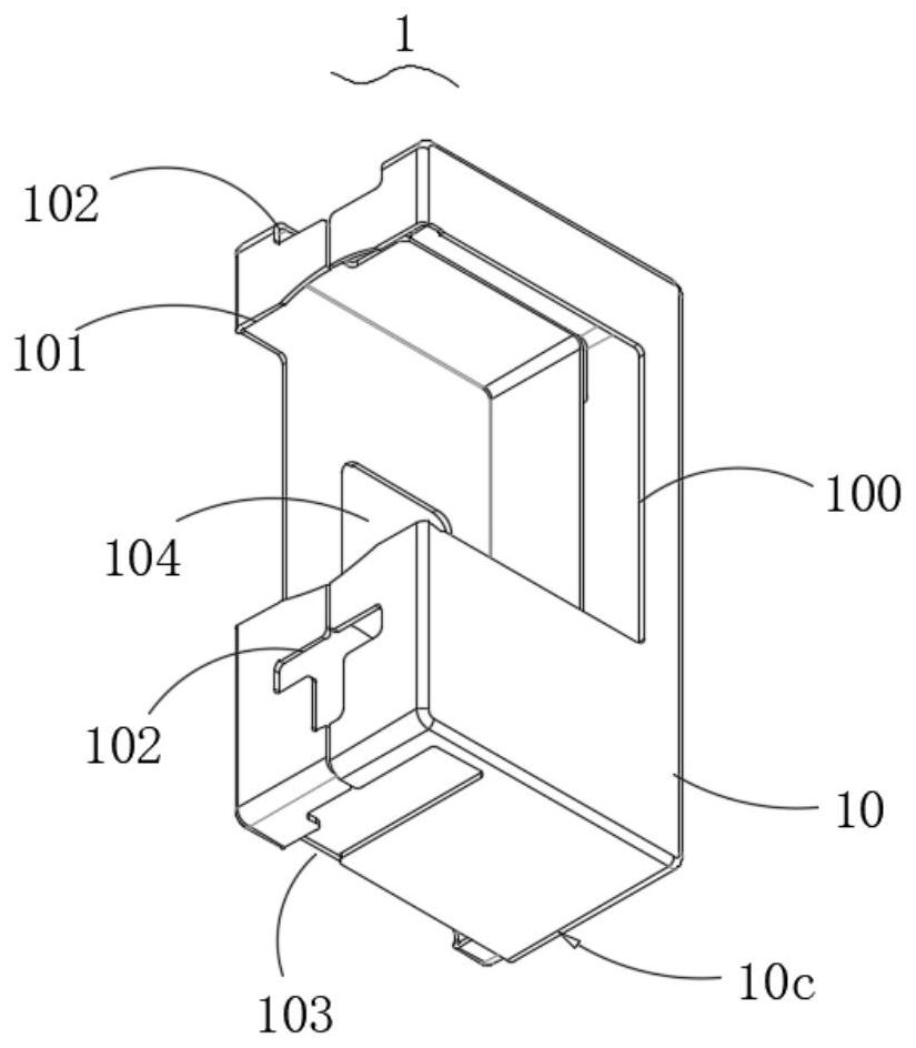
[0198] On the basis of the first embodiment above, as Figure 4 and Figure 9 As shown, the present invention also provides an optical component driving mechanism L. The arrows in the figure represent the light-incoming and light-emitting directions. The optical component driving mechanism is used to adjust the X/Y-axis position of the prism L0 to meet the use requirements. This embodiment has the housing 1 and the base 2 as described in the first embodiment above, and the circuit board 3 is fixed on the base 2. There is a single-carrier accommodation space in the base 2, and the single-carrier 4 is installed in the single-carrier accommodation space through an elastic support mechanism. In this embodiment, a Y-axis electromagnetic drive mechanism and an inclined X-axis electromagnetic drive mechanism are provided to drive the single carrier 4 .
Example Embodiment
[0199] Embodiment three
[0200] On the basis of the above-mentioned embodiment two, as Figure 17 As shown, the present invention also provides an imaging device, which has the optical component driving mechanism L as described in the second embodiment above, and the lens driving mechanism T. The lens driving mechanism T is located at the light exit port 101. Using the optical component driving mechanism L Changing the optical path and synergizing with the lens driving mechanism T can realize high-precision and ultra-clear camera work.
PUM


Description & Claims & Application Information
We can also present the details of the Description, Claims and Application information to help users get a comprehensive understanding of the technical details of the patent, such as background art, summary of invention, brief description of drawings, description of embodiments, and other original content. On the other hand, users can also determine the specific scope of protection of the technology through the list of claims; as well as understand the changes in the life cycle of the technology with the presentation of the patent timeline. Login to view more.
Similar technology patents
Method for preparing high-viscosity silicon-steel grade magnesium oxide
Owner:上海实业振泰化工有限公司
Two-degree-of-freedom large-stroke high-peed and high-precision positioning platform
InactiveCN101858477AImprove driving precisionReduce size and complexity
Owner:郑福胜
Novel flexible lead-radiation-free protective clothing
Owner:南京核安核能科技有限公司
Displacement-crawler-type pipe dredging robot
Owner:CHINA UNIV OF GEOSCIENCES (WUHAN)
Forest fire detection device
Owner:XIAN ZHONGZHI HUIZE PHOTOELECTRIC TECH
Piezoelectric inertia and piezoelectric worm-creep hybrid rotary driver
PendingCN110707962ALarge driving strokeImprove driving precision
Owner:GUANGDONG UNIV OF TECH
Classification and recommendation of technical efficacy words
- Improve driving precision
Two-degree-of-freedom large-stroke high-peed and high-precision positioning platform
InactiveCN101858477AImprove driving precisionReduce size and complexity
Owner:郑福胜
Piezoelectric inertia and piezoelectric worm-creep hybrid rotary driver
PendingCN110707962ALarge driving strokeImprove driving precision
Owner:GUANGDONG UNIV OF TECH