
Novel LED light source

A LED light source, a new type of technology, applied in the direction of electrical components, electrical solid devices, circuits, etc., can solve the problem of single color temperature, etc., and achieve the effects of convenient preparation, high driving precision, and simple structure

Pending Publication Date: 2020-06-09
轻工业部南京电光源材料科学研究所
View PDF0 Cites 2 Cited by
  • Summary
  • Abstract
  • Description
  • Claims
  • Application Information

AI Technical Summary

Problems solved by technology

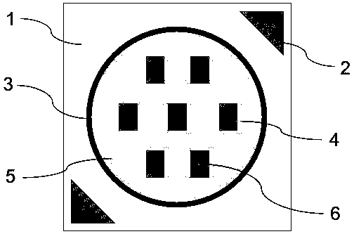
[0007] Aiming at the problems existing in the prior art, the present invention provides a new type of LED light source. The LED R, G and B chips are respectively packaged by two kinds of glues. A single problem, realizing the multi-application performance of a light source with different and fixed scene changes; at the same time, the LED light source can correct and compensate the color fading and color shift problems of the long-term use of the existing high-power LED light source by adding LED R and G chips

Method used


Image

  • Novel LED light source
  • Novel LED light source
  • Novel LED light source

Examples


Embodiment 1

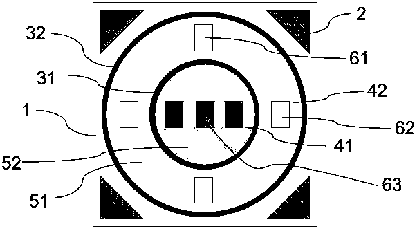
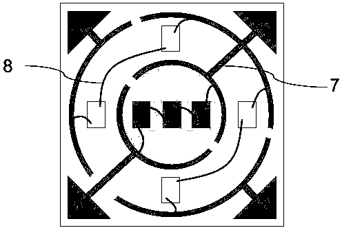
[0034] Such as figure 2 As shown, the LED light source is a COB common anode structure. The COB substrate 1 includes four electrode soldering pins 2, one of which is connected to the positive pole and three of which are connected to the negative pole. The substrate 1 is also provided with an inner pad 41 and an outer pad 42. The electrodes Welding wires 7 are arranged around the pads and communicate with the electrode soldering pins 2 respectively. Multiple groups of LED blue light chips 63 are fixed on the pads 41 through crystal bonding glue, and multiple groups of LED red and green chips are fixed on the pads 42. Above, the positive and negative poles of the LED chip are conducted through the conductive lead wire 8 or the conductive material and the electrode welding leg wire 7. The specific connection method is as follows: image 3 As shown, the positive poles of the LED R, G, and B chips are all connected to the common positive pole of the welding pin, and the negative p...

Embodiment 2

[0037] Such as Figure 4 As shown, and with reference to Embodiment 1, the structure of the LED light source is changed from square to hexagonal, and the number of electrode welding feet is increased to six. In addition, the difference from Embodiment 1 lies in that the LED chips of the same type are each positive, The negative electrode is respectively connected to the positive and negative electrodes of one of the welding legs, and the others are the same.

Embodiment 3

[0039] Such as Figure 5 As shown, and with reference to Embodiment 1, the difference from Embodiment 1 is that multiple groups of LED blue light chips 63 are fixed on the pad 42 by die-bonding glue, and multiple groups of LED red light and green light chips are fixed on the pad 41 Above; glue 51 is dispensed and packaged at the inner dam 31, and glue 52 is packaged between the dams 31 and 32, and the others are the same.


PUM


Abstract

The invention discloses a novel LED light source. The novel LED light source is characterized in that the novel LED light source is of a COB structure and comprises a COB substrate, an LED red light chip, an LED green light chip, an LED blue light chip, two packaging box dams with different sizes, a packaging glue and the like; the COB substrate is provided with an inner side bonding pad, an outerside bonding pad, four or six electrode welding pins, electrode welding pin wires and the like, wherein the inner side bonding pad and the outer side bonding pad are used for placing LED chips; the packaging glue comprises transparent glue and fluorescent powder adding glue; the LED chips are installed on the bonding pads of the COB substrate respectively and are conductively connected to the electrode welding pins; the packaging box dams are filled with the two kinds of packaging glue respectively; and the LED light source is obtained after solidification is performed. According to the novelLED light source of the invention, the LED light source is packaged through the two kinds of glue; the color temperature and the light color of the obtained LED light source can be adjusted at will,so that the problem that the color temperature of an existing LED light source is single is solved, and the multi-application performance of such a light source in different and fixed scene changes isachieved; the LED light source is additionally provided with the LED red chip and the LED green chip, so that the problems of color attenuation and color shift of an existing high-power LED light source in long-term use can be correct and offset.

Description

technical field [0001] The invention belongs to the field of semiconductor lighting, in particular to the field of a novel LED light source. Background technique [0002] As a new type of lighting product, LED has the advantages of energy saving, environmental protection, long life, and low cost compared with traditional lighting, so it has been extensively researched, developed and utilized in recent years. [0003] Existing LED lighting sources are mainly prepared by exciting yellow phosphor powder with LED blue light (B) chips. The blue light chip generates red light (R) and green light (G) by exciting yellow phosphor powder, and then mixes with the remaining blue light to obtain a certain White light with one color temperature. Compared with using R, G, and B chips to emit light and mix colors, this method is simple, convenient and low in cost. [0004] At the same time, the structure of the existing LED lighting source is mainly SMD and COB. Among them, the COB structu...

Claims


Application Information

Patent Timeline
Patent Type & Authority Applications(China)
IPC IPC(8): H01L25/075H01L33/54H01L33/56H01L33/50H01L33/62
CPCH01L25/0753H01L33/54H01L33/56H01L33/50H01L33/62
Inventor 刘晓锋蒋腾尤宇财童嘉俊卓宁泽刘光熙郭健王海波
Owner 轻工业部南京电光源材料科学研究所
Learn More