
Light polarization infinite tracking control method and system

A tracking control and optical polarization technology, applied in the field of optical communication, can solve the problems of high cost and power consumption, unable to realize infinite tracking and stable control of optical polarization state, and achieve the effect of low cost, infinite tracking control and easy realization.

Active Publication Date: 2021-07-09
SUN YAT SEN UNIV
View PDF6 Cites 0 Cited by
  • Summary
  • Abstract
  • Description
  • Claims
  • Application Information

AI Technical Summary

Problems solved by technology

However, the cost and power consumption of the coherent detection scheme are too high, and the infinite tracking and stable control of the polarization state of light cannot be realized.

Method used


Image

  • Light polarization infinite tracking control method and system
  • Light polarization infinite tracking control method and system
  • Light polarization infinite tracking control method and system

Examples


Embodiment

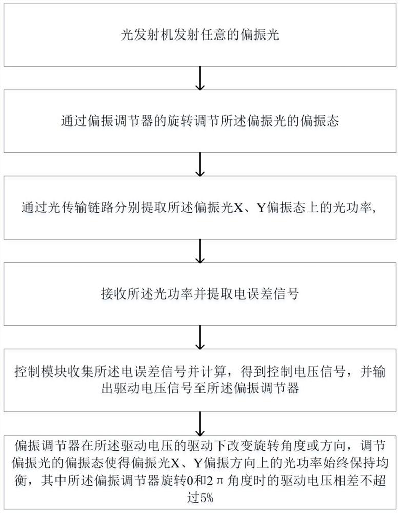
[0043] Such as figure 1 It is an embodiment of an optical polarization infinite tracking control method, including:

[0044] S1: The optical transmitter emits arbitrary polarized light;

[0045] S2: adjusting the polarization state of the polarized light through the rotation of the polarization adjuster;

[0046] S3: Extract the optical power E on the polarized light X and Y polarization states respectively through the optical transmission link X ,E Y

[0047] S4: Receive E X ,E Y optical signal and extract the electrical error signal;

[0048]S5: The control module collects and calculates the electrical error signal, obtains the control voltage signal, and outputs the driving voltage signal to the polarization adjuster;

[0049] S6: The polarization adjuster changes the rotation angle or direction under the drive of the driving voltage, and adjusts the polarization state of the polarized light so that the optical power in the X and Y polarization directions of the pola...


PUM


Abstract

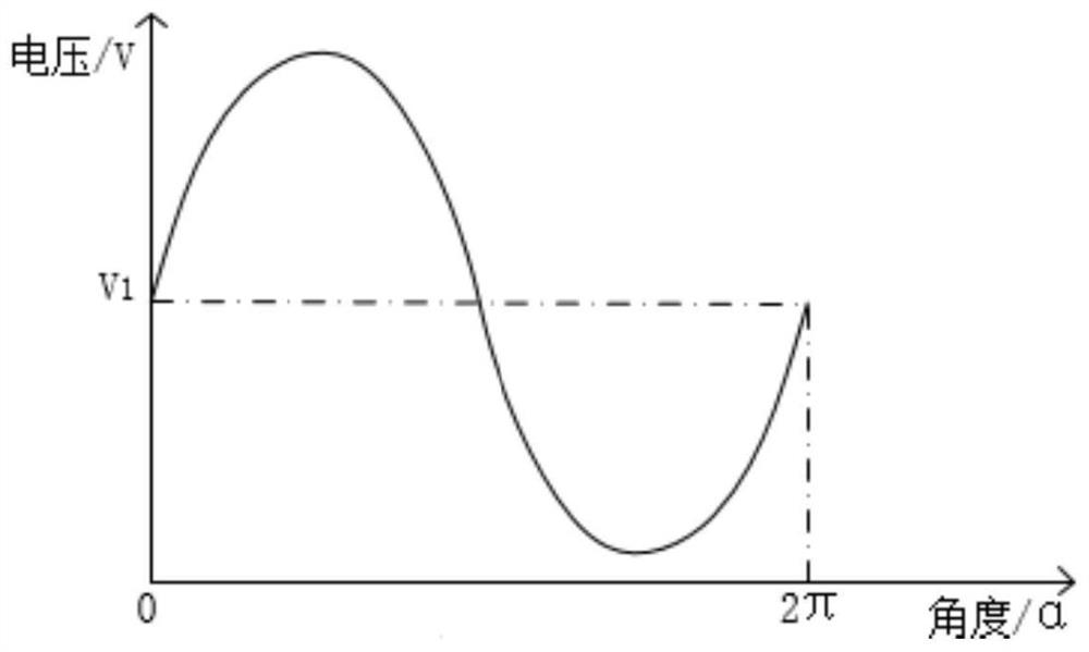
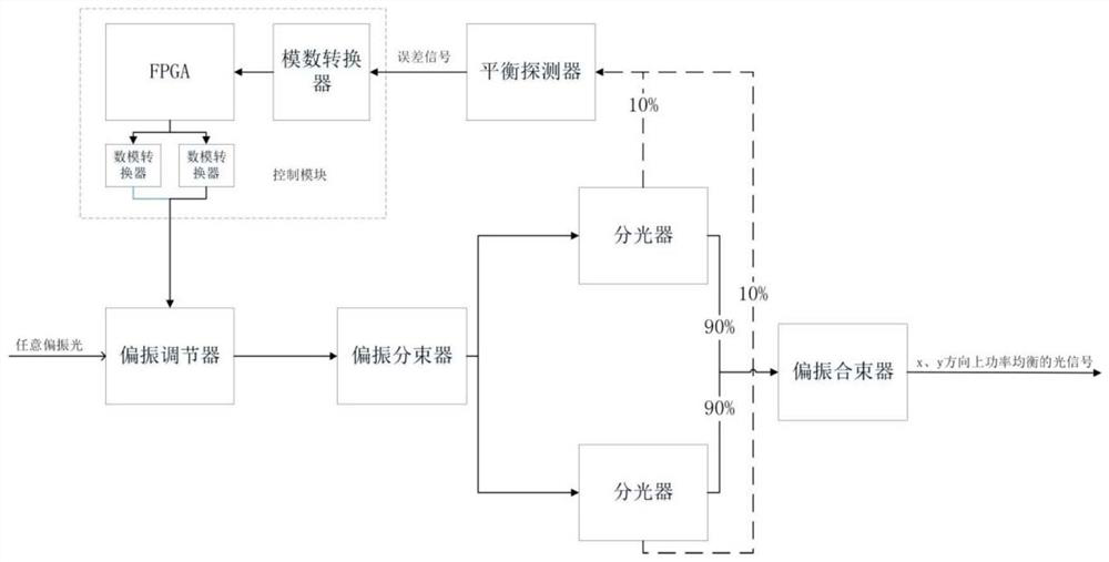
The invention belongs to the technical field of optical communication, and more particularly relates to a light polarization infinite tracking control method and system. The method comprises the steps that: S1, an optical transmitter transmits any polarized light; the polarization state of the polarized light is regulated through rotation of a polarization regulator; the optical power EX and EY of the polarized light in X and Y polarization states are extracted through an optical transmission link; EX and EY optical signals are received, and electrical error signals are extracted; a control module collects the electrical error signals and performs calculation to obtain a control voltage signal and outputs a driving voltage signal to the polarization regulator; and the polarization regulator changes the rotation angle or direction under the driving of the driving voltage and regulates the polarization state of the polarized light to enable the optical power of the polarized light in the X and Y polarization directions to be always kept balanced, wherein the driving voltage difference does not exceed 5% when the polarization regulator rotates by an angle of 0 and 2 pi. According to the scheme, infinite tracking control of light polarization can be realized, and meanwhile, the system cost can be reduced.

Description

technical field [0001] The invention belongs to the technical field of optical communication, and more specifically relates to an optical polarization infinite tracking control method and a system thereof. Background technique [0002] The growth of data center traffic has become a major part of today's global Internet Protocol (IP) traffic. It needs to use high-capacity optical interfaces for interconnection and network between data centers. Therefore, it is expected that there will be a capacity requirement of 800GE or even 1.6TBE in the future. Intensity Modulation and Direct Detection (IMDD) systems using Coarse Wavelength Division Multiplexing (CWDM) are still preferred for short distance applications in interconnection between data centers and networks due to its simplicity and low cost . However, limited by the use of wavelengths and bandwidth density, it is difficult to cope with the endless increase in data rate requirements of data centers. Traditional coherent ...

Claims


Application Information

Patent Timeline
IPC IPC(8): G05D3/20H04B10/516
CPCG05D3/20H04B10/516
Inventor 王大伟雷宇赖开琴李朝晖
Owner SUN YAT SEN UNIV
Learn More