

Visual odometer pose optimization method based on highlight pixel detection
A technology of visual odometry and optimization method, applied in the directions of calculation, image enhancement, image analysis, etc., can solve the problems of image matching error and decreased positioning accuracy, and achieve the effect of improving positioning accuracy and avoiding high-light pixels.
- Summary
- Abstract
- Description
- Claims
- Application Information
AI Technical Summary
Problems solved by technology
Method used
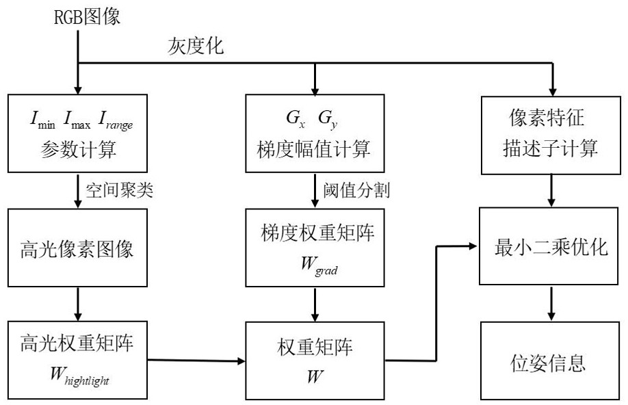
Image

Examples
Embodiment Construction
[0043] Specific embodiments of the present invention will be described in detail below in conjunction with the accompanying drawings. It should be understood that the specific embodiments described here are only used to illustrate and explain the present invention, and are not intended to limit the present invention.
[0044] Such as figure 1 Shown, concrete implementation of the present invention is as follows:
[0045] S1: The camera is mounted on a mobile platform, its position and angle of view are fixed, and the environmental color image information is obtained in real time according to a fixed number of frames;
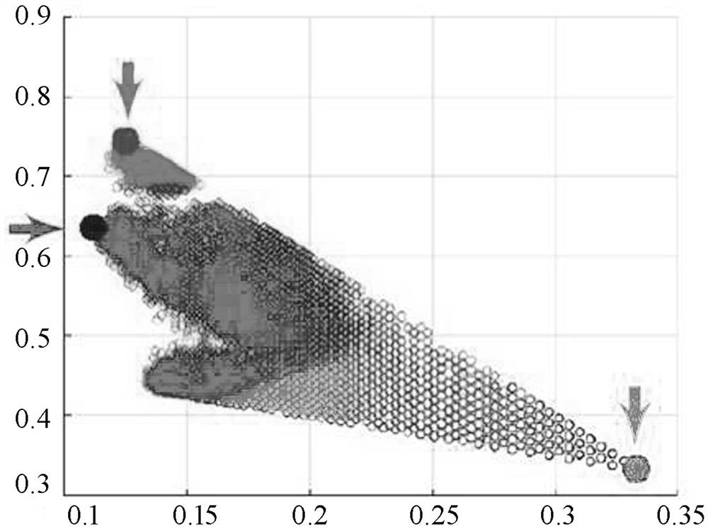
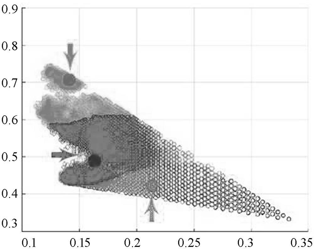
[0046] S2: Calculate the highlight pixel image in the color image: Calculate the minimum intensity of the color image I min , the maximum intensity I max , chromaticity value Λ psf ( i ), introduce the corresponding chromaticity values of all pixels into the minimum chromaticity-maximum chromaticity two-dimensional space for clustering, and calculate a...
PUM
 Abstract
Description
Claims
Application Information