A LED display video transmission method

A technology of LED display and video transmission, which is applied in the direction of cable transmission adaptation, television system adapted to optical transmission, static indicators, etc. It can solve problems such as poor anti-interference ability, error packet loss, and difficulty in realizing thin and light equipment design. , to improve the stability of the

Active Publication Date: 2021-08-27
CHENGDU CHENGDIAN GUANGXIN TECH
View PDF21 Cites 0 Cited by
  • Summary
  • Abstract
  • Description
  • Claims
  • Application Information

AI Technical Summary

Problems solved by technology

The existing drive scheme has the following problems: 1. There are too many cables between the video sending device and the LED display screen, which makes installation and maintenance difficult; 2. The connection of the system equipment is complicated, the reliability and stability are poor, and there is no redundant design. Once the video sending device fails, the entire screen cannot be displayed; 3. The sending device and the receiving device are designed separately, which makes it difficult to realize the light and thin design of the device; 4. After the video is divided, it is transmitted to the corresponding display module through different network cables. The data between them is prone to jitter, which causes the display between the modules to be out of sync; 5. Due to the long-distance electrical signal transmission, the delay is relatively large, and the anti-interference ability is poor, and it is easy to be interfered, resulting in error packet loss
In the existing technology represented by the above-mentioned patent documents, the scanning card is similar to the video receiving card, and the scanning card and the LED light board form an LED display unit board, and each string of LED display unit boards has one LED display unit board or cascaded multiple LED display unit boards. However, in this prior art, the video is still sent to the distributor through the sending card, and then the distributor divides and transmits the video to the LED display unit board, and the network cable is also used for transmission between the distributors.
It still has the following technical defects: both the sending card and the distributor are set outside the LED display module, exist independently, and are set separately from the LED display module, that is, they still exist independently like the traditional video sending card, However, the scanning card is integrated inside the LED display module. After the video is divided by the distributor, it is transmitted to the corresponding LED display unit boards through different network cables. The data between the LED display unit boards is prone to jitter, causing the LED display unit board Technical defects such as out-of-sync display between

Method used


Image

  • A LED display video transmission method
  • A LED display video transmission method

Examples


Embodiment 1

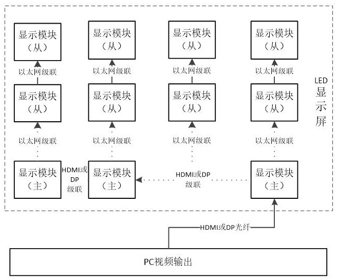
[0030] As a preferred embodiment of the present invention, see figure 1 , the invention discloses a LED display video transmission method, the specific steps are as follows:

[0031] S1. Set a master LED display module and a slave LED display module on the LED display, and cascade between multiple master LED display modules to form a row for data transmission. Between each master LED display module and at least one slave LED display module Through Ethernet cascading to form a column for data transmission, integrate the sending device, receiving device and LED light board on the master LED display module, and integrate the receiving device and LED light board on the slave LED display module;

[0032] The secondary LED display modules of any two columns are independent from the secondary LED display modules;

[0033] S2. After the video source data input from the outside is processed by the sending device, one channel of video source data is sent to the receiving device in the ...

Embodiment 2

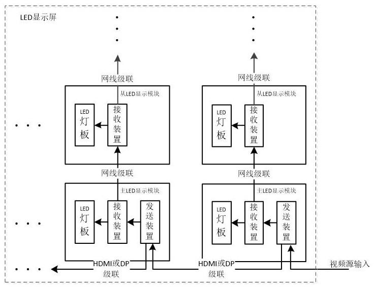
[0038] As another preferred embodiment of the present invention, on the basis of Example 1, see figure 2 After the video source data is processed by the sending device, the position number information is added in the blanking area of ​​the video source data, and after the sending device of the main LED display module of the next level receives the video source data of the sending device of the upper level, the blanking is analyzed The position number signal of the area, and the position number is incremented by 1, thereby determining the position of each sending device in the LED display screen, and intercepting the video source data that needs to be displayed in the corresponding column where the main LED display module of this level is located for driving display .

[0039] Compared with the prior art, the problem of cutting and distributing video source data between multiple main LED display modules in the same row is truly realized, and the video source data between each ...

Embodiment 3

[0041] As another preferred embodiment of the present invention, on the basis of Example 1, see figure 2 , in the main LED display module of this level, when the sending device sends the intercepted video source data to the receiving device, the position number information is added, and the receiving device of the main LED display module sends the information to the receiving device of the next level slave LED display module in this column. When sending data, the position number is incremented by 1, thereby determining the position of each receiving device in the LED display screen, and intercepting the column from the video source data that the LED display module needs to display for drive display.

[0042] Compared with the prior art, the problem of intercepting and distributing video source data between multiple slave LED display modules in the same column is truly realized, and the video source data between each slave LED display modules will not have any interference and ...


PUM


Abstract

The invention discloses a LED display video transmission method, which relates to the technical field of video data transmission. A master LED display module and a slave LED display module are arranged on an LED display screen, and a plurality of master LED display modules are cascaded to form a row for data transmission. Transmission, each master LED display module and at least one slave LED display module are cascaded through Ethernet to form a column for data transmission; after the video source data input from the outside is processed by the sending device, one channel of video source data is sent to the current level The receiving device in the main LED display module performs processing, and the other video source data is sent to the sending device in the next-level main LED display module for processing; this method decentralizes the video sending function and improves the stability of the display effect. At the same time, the data between the various display modules will not produce delay jitter and line interference, and there will be no phenomena such as display asynchrony or screen tearing.

Description

technical field [0001] The invention relates to the technical field of video data transmission, in particular to an LED display video transmission method. Background technique [0002] At present, the LED display drive field mostly adopts a decentralized drive layout, that is, the entire display system is divided into a video sending device and a video receiving device. The video sending device exists independently, and the video receiving device is integrated inside the display module. The video source transmits 4K high-definition images to the video sending device through the HDMI or DP interface. Since the video sending device is on the PC side and away from the screen, the video sending device is used to divide the video screen, and then through several Gigabit network cables, the The display data in different areas of the video are transmitted to the corresponding LED display modules respectively. The existing drive scheme has the following problems: 1. There are too m...

Claims


Application Information

Patent Timeline
Patent Type & Authority Patents(China)
IPC IPC(8): G09G3/32H04N7/22H04N21/4363
CPCG09G3/32H04N7/22H04N21/43635
Inventor 解军王继岷张悦
Owner CHENGDU CHENGDIAN GUANGXIN TECH
Why Eureka
Try Eureka