
Vagina inspector

A technology of vaginal inspection and inspection device, which is applied in the field of medical devices, can solve problems such as inconvenience, and achieve the effect of improving the convenience of inspection

Active Publication Date: 2021-07-13
SUNLAND MEDICAL CO LTD
View PDF2 Cites 1 Cited by
  • Summary
  • Abstract
  • Description
  • Claims
  • Application Information

AI Technical Summary

Problems solved by technology

The existing dilator is separated from the inspector. During the inspection, the doctor must hold the inspector with his hand after putting the inspector into the dilator, which is very inconvenient.

Method used


Image

  • Vagina inspector
  • Vagina inspector
  • Vagina inspector

Examples


Embodiment 1

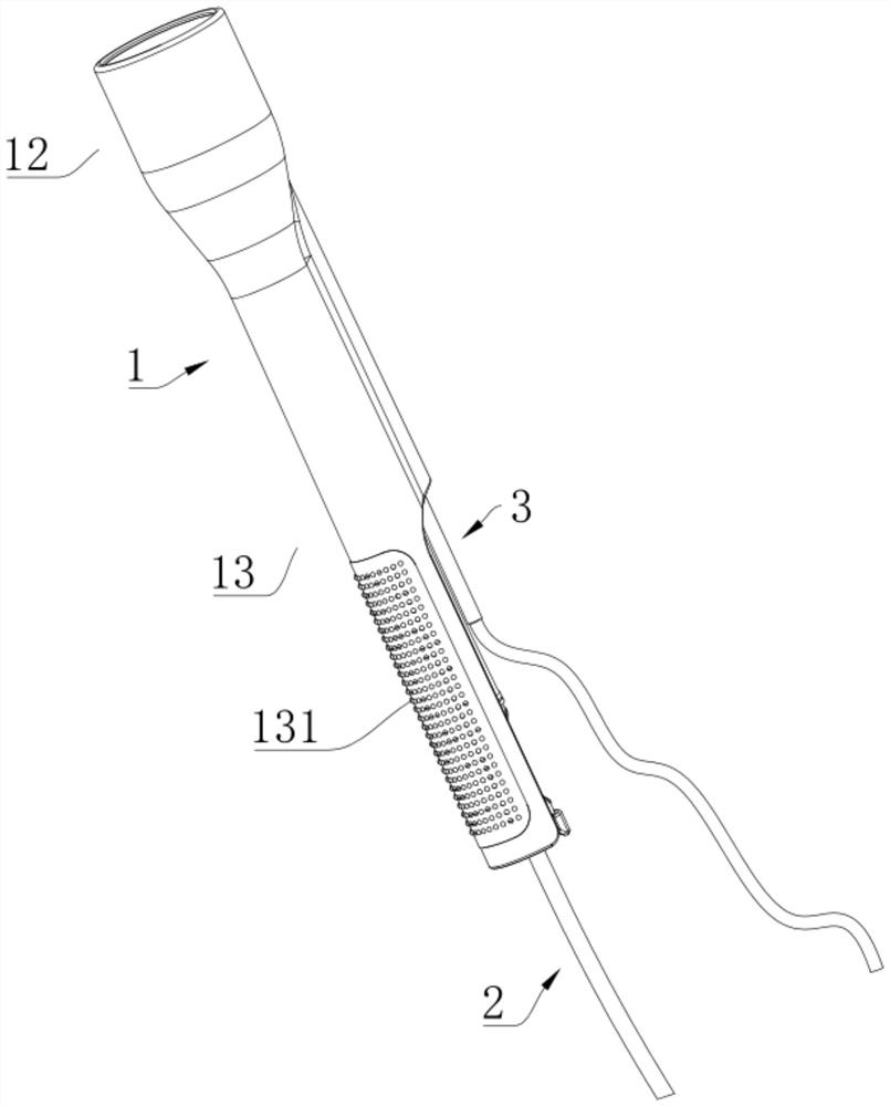
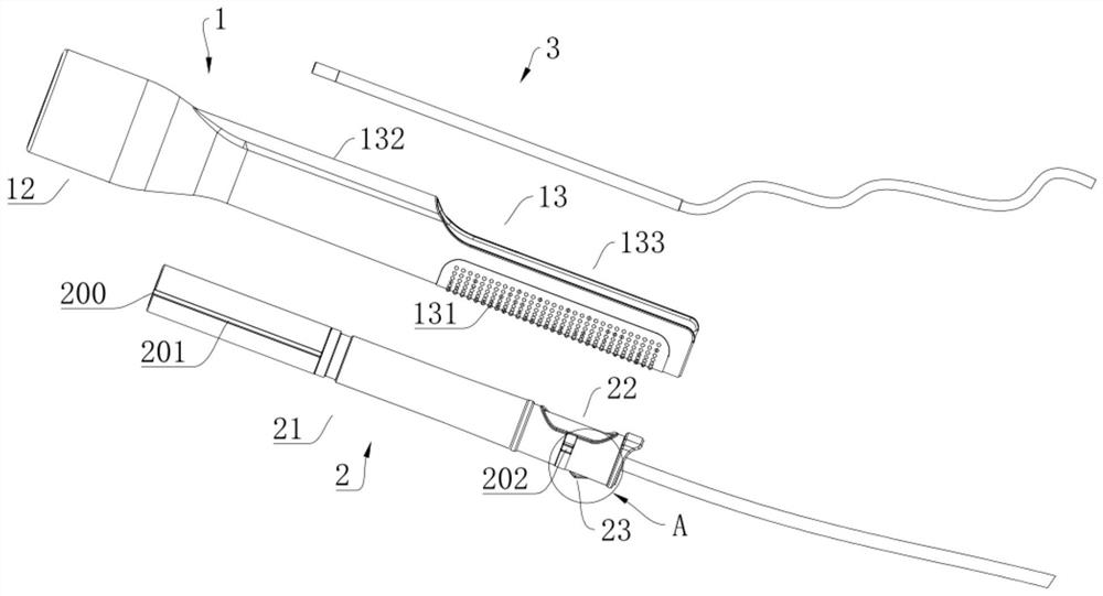
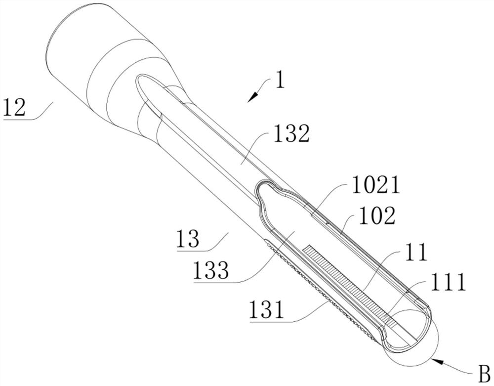
[0037] refer to Figure 1 to Figure 3 , figure 1 It is a schematic structural view of the vaginal tester in the embodiment, figure 2 is an exploded view of the vaginal examiner in the embodiment, image 3 It is a schematic diagram of the structure of the dilator in the embodiment. The vaginal tester in this embodiment includes a dilator 1 and a tester 2 arranged in the test channel. An inspection channel is formed inside the dilator 1; an inspection moving path 11 is also provided inside the dilator 1 along the direction of the inspection channel. The inspector 2 includes a protective assembly 21, an inspection assembly 22, and an elastic movement assembly 23. The protection assembly 21 is sleeved outside the inspection assembly 22, and the elastic movement assembly 23 is arranged on the protection assembly 21 and connects with the inspection movement path 11; 21 exerts an active force to drive the inspection component 22 to move in the inspection channel, the elastic mov...

Embodiment 2

[0054] refer to Figure 10 , Figure 10 It is a structural schematic diagram of another dilator in the embodiment. The difference between the vaginal tester in this embodiment and the first embodiment is that: the end of the expansion end 12 away from the leading end 13 has a cervical os slope structure 121 . The dilating end 12 of the dilator 1 is adapted to dilate the cervical os through the setting of the inclined surface structure 121 of the cervix, thereby facilitating subsequent inspections. The inclined surface structure 121 of the cervical os in this embodiment specifically forms a curved mouth shape suitable for the cervix at the position where the expansion end 12 is away from the leading end 13 .

[0055] Continue to refer to Figure 11 to Figure 14 , Figure 11 It is a cross-sectional view of another checker in the embodiment, Figure 12 is an exploded view of another inspector in the example, Figure 13 For example Figure 11 Enlarged view of C, Figure 14...


PUM


Abstract

The invention discloses a vagina inspector, which comprises an expander with an inspection channel and an inspector body, wherein an inspection moving path is arranged in the expander, the inspector body comprises a protection assembly, an inspection assembly and an elastic moving assembly, the inspection assembly is sleeved with the protection assembly, and the elastic moving assembly is arranged on the protection assembly, and is connected with the inspection moving path. Acting force is applied to the protection assembly, the inspection assembly is driven to move in the inspection channel, the elastic moving assembly moves on the inspection moving path, the force applied to the protection assembly is removed, and the elastic moving assembly abuts against the inspection moving path, so that the inspection assembly is stably fixed in the inspection channel. According to the inspector, through the conversion of the two matching modes of relative movement and mutual abutting between the elastic moving assembly and the inspection moving path, the inspection assembly can flexibly move in the inspection channel and be stabilized at a certain position, a doctor can conduct inspection without holding the inspection device with the hand, and the inspection convenience is improved.

Description

technical field [0001] The invention relates to the technical field of medical devices, in particular to a vaginal tester. Background technique [0002] When performing gynecological disease examinations, doctors often need to use a vaginal tester for inspection. Generally, the vagina is first expanded by a dilator, and then the tester is inserted into a suitable position in the vagina for inspection. The existing dilator is separated from the checker. When checking, the doctor must hold the checker with his hands after putting the checker into the dilator, which is very inconvenient. Contents of the invention [0003] Aiming at the deficiencies of the prior art, the invention provides a vaginal tester. [0004] A vaginal tester disclosed in the present invention includes a dilator, an inspection channel is formed inside it; an inspection moving path is also arranged inside the dilator along the direction of the inspection channel; and [0005] An inspector installed in ...

Claims


Application Information

Patent Timeline
IPC IPC(8): A61B1/015A61B1/303A61M31/00A61B1/32
CPCA61B1/015A61B1/303A61M31/00A61B1/32A61B1/00096A61B1/00163
Inventor 张洋魏信鑫
Owner SUNLAND MEDICAL CO LTD
Learn More