
Anti-blocking mechanism of magnetic turning plate liquid level meter

A magnetic flap liquid level and liquid level gauge technology, applied in the field of liquid level gauges, can solve the problems of disassembly affecting the continuous detection of the measured medium, cumbersome, mesh clogging, etc., to reduce the possibility of embedding and clogging the filter, prevent The effect of being blocked and easy to disassemble and replace

Pending Publication Date: 2021-07-13
ANHUI CHUNHUI INSTR CABLE GROUP
View PDF7 Cites 2 Cited by
  • Summary
  • Abstract
  • Description
  • Claims
  • Application Information

AI Technical Summary

Problems solved by technology

[0005] Aiming at the deficiencies of the prior art, the present invention provides an anti-blocking mechanism of the magnetic flap liquid level gauge, which can quickly clean up the solid particle impurities embedded in the filter screen to prevent blockage, and does not need to be disassembled, and is relatively simple and convenient to use. It is beneficial to the continuous detection of the measured medium, and solves the problem that solid particles and impurities enter the liquid level gauge by installing a filter. However, when the filter is used for a long time, solid particles are easily embedded in the mesh and cause blockage. , it is generally necessary to disassemble the filter for replacement, which is not only cumbersome, but also disassembly will affect the continuous detection of the measured medium. Therefore, a problem of an anti-blocking mechanism of the magnetic flap level gauge is proposed

Method used


Image

  • Anti-blocking mechanism of magnetic turning plate liquid level meter
  • Anti-blocking mechanism of magnetic turning plate liquid level meter
  • Anti-blocking mechanism of magnetic turning plate liquid level meter

Examples


Embodiment Construction

[0023] The following will clearly and completely describe the technical solutions in the embodiments of the present invention with reference to the accompanying drawings in the embodiments of the present invention. Obviously, the described embodiments are only some, not all, embodiments of the present invention. Based on the embodiments of the present invention, all other embodiments obtained by persons of ordinary skill in the art without making creative efforts belong to the protection scope of the present invention.

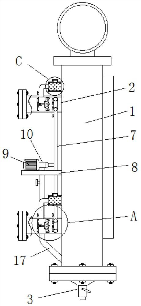
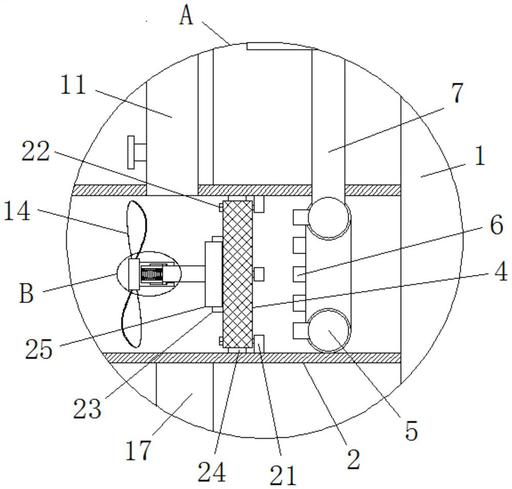
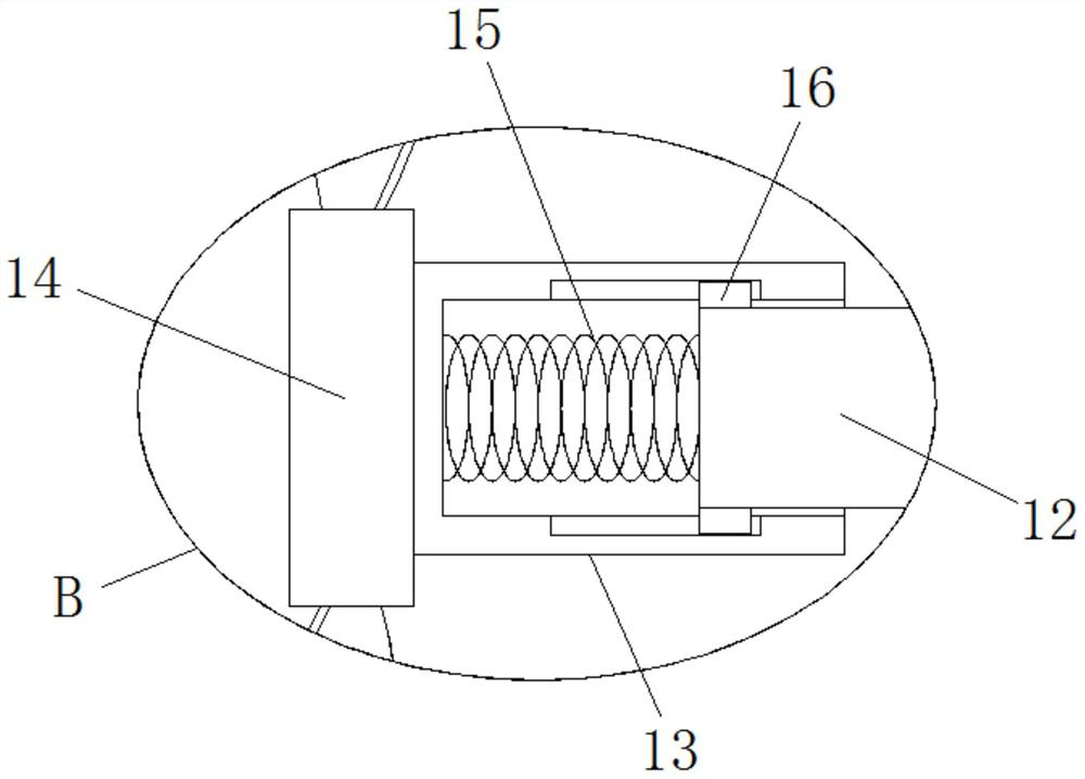
[0024] see Figure 1-4 , an anti-blocking mechanism for a magnetic flap liquid level gauge, comprising a liquid level gauge body 1, the liquid level gauge body 1 includes two installation pipes 2 and a drain valve 3, and the inner right sides of the two installation pipes 2 are connected with installation mechanism and is connected with a filter screen 4 through the installation mechanism, and the inside of the two installation pipes 2 is located at the right ...


PUM


Abstract

The invention relates to the technical field of liquid level meters, and discloses an anti-blocking mechanism of a magnetic turning plate liquid level meter. The anti-blocking mechanism comprises a liquid level meter body, which comprises two mounting pipes and a blow-down valve, wherein the right sides of the interiors of the two mounting pipes are connected with mounting mechanisms and are connected with filter screens through the mounting mechanisms, annular pipes are fixedly arranged at the positions, located on the right sides of the filter screens on the same sides, in the two mounting pipes, a plurality of evenly-distributed jet pipes are fixedly connected to the left sides of the pipe walls of the two annular pipes, a T-shaped connecting pipe is jointly and fixedly communicated between the two annular pipes, and a mounting plate is fixedly connected to the left outer side wall of the liquid level meter body. According to the anti-blocking mechanism of the magnetic turning plate liquid level meter, solid particle impurities embedded in the filter screen can be rapidly cleaned so as to prevent the blocking phenomenon, disassembly is not needed so as to facilitate the continuous detection of a detected medium, and the situation that due to the fact that the flow speed of the medium is too high, the magnetic floater excessively floats up and down, and observation of the detection effect is affected can be prevented.

Description

technical field [0001] The invention relates to the technical field of liquid level gauges, in particular to an anti-blocking mechanism of a magnetic flap liquid level gauge. Background technique [0002] The magnetic flap level gauge is developed according to the principle of buoyancy and magnetic coupling. The instrument can be used for medium liquid level detection of various towers, tanks, tanks, spherical containers and boilers. It can be directly used to observe the liquid level of the medium in various containers, and it is suitable for liquid level indication in petroleum, chemical and other industrial fields. [0003] At present, when the magnetic flap detects the liquid level, the solid impurities in the measured medium often enter the inside of the liquid level gauge along with the fluid. On the one hand, if the solid impurities adhere to the magnetic float or the inner wall of the liquid level gauge tube, It is easy to cause the magnetic float to fail to move sm...

Claims


Application Information

Patent Timeline
IPC IPC(8): B01D29/03B01D29/54B01D29/68G01F23/72
CPCB01D29/03B01D29/54B01D29/68G01F23/72
Inventor 沈必亮
Owner ANHUI CHUNHUI INSTR CABLE GROUP
Learn More