Clamping device and machining equipment provided with same

A clamping device and clamping surface technology, applied in the field of mechanical processing, can solve the problems of reducing the surface roughness of the workpiece, increasing the process, and low work efficiency, so as to achieve the effect of improving processing efficiency

Active Publication Date: 2021-07-13
FAW JIEFANG AUTOMOTIVE CO
View PDF5 Cites 0 Cited by
  • Summary
  • Abstract
  • Description
  • Claims
  • Application Information

AI Technical Summary

Benefits of technology

This device allows for secure fixing while also allowing multiple tools or other objects that require precise positional control on their own are being worked together more efficiently than if they were individually controlled. It uses two types of clamps: one holds an object between them (side-clamps) and another fixes it against its holder(s). By doing this, there're no longer any obstacles when working around these things at once, which makes it faster and easier to perform tasks like cutting materials accurately. Additionally, the use of both sides helps prevent excessive heat from affecting certain areas inside the machine due to insufficient coolant flow caused by lack of space near each area where the temperature needs to stay within acceptable limits. Overall, this technology enhances productivity and quality.

Problems solved by technology

The technical problem addressed in this patented text relates to improving the accuracy and speed at which car body manufacturing involves machining complex shapes on top surfaces during trials or stages where there may be other objects that obstruct access from certain areas around them (such as tools). Existing methods require adjustment after each part has been milled, leading to lower throughput compared to current methods without these modifications.

Method used


Image

  • Clamping device and machining equipment provided with same
  • Clamping device and machining equipment provided with same
  • Clamping device and machining equipment provided with same

Examples


Embodiment Construction

[0037] In order to make the above objects, features and advantages of the present invention more comprehensible, specific implementations of the present invention will be described in detail below in conjunction with the accompanying drawings. In the following description, numerous specific details are set forth in order to provide a thorough understanding of the present invention. However, the present invention can be implemented in many other ways different from those described here, and those skilled in the art can make similar improvements without departing from the connotation of the present invention, so the present invention is not limited by the specific embodiments disclosed below.

[0038] In describing the present invention, it should be understood that the terms "center", "longitudinal", "transverse", "length", "width", "thickness", "upper", "lower", "front", " Back", "Left", "Right", "Vertical", "Horizontal", "Top", "Bottom", "Inner", "Outer", "Clockwise", "Counte...


PUM


Abstract

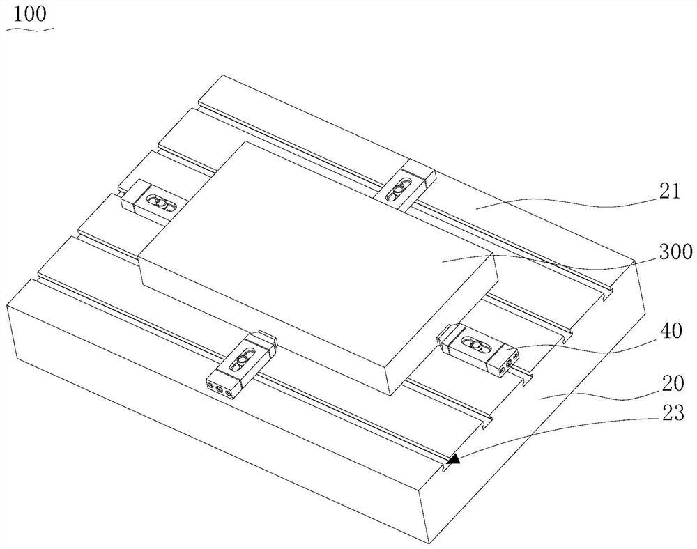
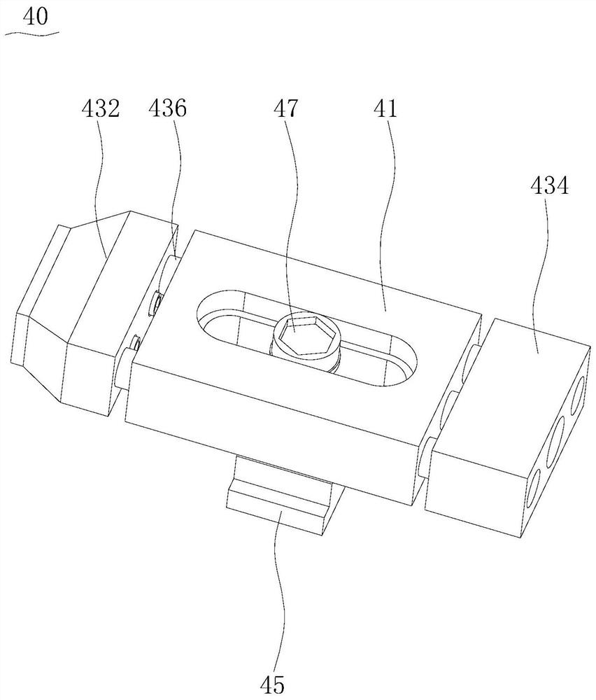
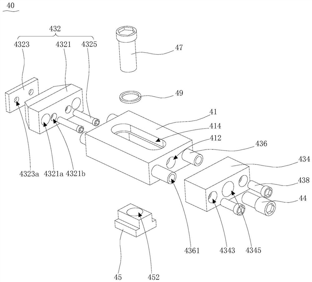
The invention relates to a clamping device and machining equipment provided with the same. The clamping device comprises a workbench with a working face; at least two clamping units which are detachably installed on the workbench, wherein each clamping unit is provided with a lateral clamping face intersecting with the working face and a forward clamping face parallel to the working face, and the lateral clamping face and/or the lateral clamping face and the working face jointly define a limiting space used for clamping a workpiece; and the lateral clamping face can move relative to the workbench in the direction parallel to the working face, and the forward clamping face can move relative to the workbench in the direction parallel to the working face and the direction perpendicular to the working face. According to the clamping device of the invention, the workpiece can be fixed together through the workbench and the clamping units, and compared with the prior art that a pressing plate is adopted to conduct forward pressing on the workpiece, due to the fact that the clamping units can conduct lateral clamping on the workpiece through the lateral clamping face, interference with the machining path of a cutter is avoided, and the pressing plate does not need to be moved in the machining process, therefore, the machining efficiency is improved.

Description


Claims


Application Information

Patent Timeline
Owner FAW JIEFANG AUTOMOTIVE CO
Why Eureka
Try Eureka