Method for forming carbon fiber composite parts with large shaft-to-diameter ratio

A composite material and carbon fiber technology, which is used in the field of forming carbon fiber composite material parts with a large axis-to-diameter ratio, can solve the problems of inability to guarantee the straightness of the forming cable, unfavorable for the tensile strength of carbon fiber, operation repeatability, poor stability, etc. , to achieve the advantages of excellent mechanical properties, stable and consistent performance, and easy guarantee of straightness.

Active Publication Date: 2022-04-26
江苏集萃碳纤维及复合材料应用技术研究院有限公司
View PDF4 Cites 0 Cited by
  • Summary
  • Abstract
  • Description
  • Claims
  • Application Information

AI Technical Summary

Problems solved by technology

[0002] It is convenient to form a rod with a large shaft-to-diameter ratio (generally 30-600) and a special-shaped structure at the end of traditional metal forming, but there is a problem of increasing the diameter of the rod in order to achieve a certain tensile strength, resulting in excessive final weight. , the use of carbon fiber composite materials can effectively reduce the weight and improve the strength
The traditional preparation method is to use the pultrusion process to prepare the middle equal-diameter rod part, and then mechanically rivet or glue the end part. This operation has poor repeatability and stability.
The connection part is easy to become a mechanical weak point, which is not conducive to the excellent tensile strength of carbon fiber
Using dry prepreg tape pultrusion winding to obtain the curing of carbon fiber composite materials is relatively large in proportion to the length of the lock body, and the investment in equipment and space is relatively large. For example, refer to the previously submitted patent (application number 202110088678.X), curing mold It is very large. The dry molding process of the research institute, the curing mold is moving, but the track for the mold movement will become larger according to the distance of the movement, occupying a large area of ​​the site, and the size of the cable is large during the movement When there is self-weight drooping, the reciprocating operation of the curing equipment is not easy to control, and the curing cannot guarantee the straightness of the forming cable. The wet forming is more efficient, borrowing existing mature equipment without development, the forming area is small, and the straightness is easy to guarantee.

Method used


Image

  • Method for forming carbon fiber composite parts with large shaft-to-diameter ratio
  • Method for forming carbon fiber composite parts with large shaft-to-diameter ratio
  • Method for forming carbon fiber composite parts with large shaft-to-diameter ratio

Examples


Embodiment Construction

[0035] The present invention is not limited to the following specific embodiments. Those skilled in the art can implement the present invention in various other specific embodiments according to the disclosed content of the present invention, or make simple changes or All changes fall within the protection scope of the present invention. It should be noted that, in the case of no conflict, the embodiments of the present invention and the features in the embodiments can be combined with each other.

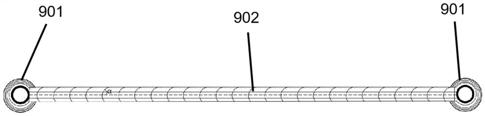
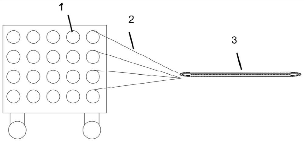
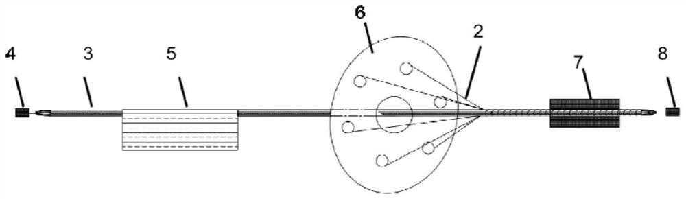
[0036] The present invention is described in further detail below in conjunction with embodiment: see Figure 2 to Figure 5 , a method for forming carbon fiber composite parts with a large shaft-to-diameter ratio, see figure 1 The carbon fiber composite material part includes an intermediate rod part and ring parts integrally formed at both ends of the rod part, and the forming method of the carbon fiber composite material part comprises the following steps:

[0037] (1) see fi...


PUM

PropertyMeasurementUnit
angleaaaaaaaaaa
tensile strengthaaaaaaaaaa

Abstract

The invention belongs to the technical field of preparation of carbon fiber composite parts, and specifically discloses a method for forming a carbon fiber composite part with a relatively large shaft-to-diameter ratio. The forming method includes: (1) reciprocating winding of continuous carbon fiber unidirectional yarn on a creel Form into a ring to obtain the dry yarn preform; (2) Under the set tension, pull and squeeze the dry yarn preform, and make the middle part pass through the resin tank to fully infiltrate the resin, the winding device to wind the fiber tow and heat and cure the mold Heat and solidify to obtain an intermediate, in which the winding angle α of the fiber tow is 30-60°, and the two ends of the intermediate form a dry yarn ring; the dry yarn ring is subjected to secondary wet molding under a set radial tension Molded into a ring portion, the radial tension is equal to the tension in step (2). The molding method of the invention has higher efficiency, borrows the existing mature equipment without development, has a small footprint for molding, and is easy to ensure straightness.

Description

technical field [0001] The invention belongs to the technical field of preparation of carbon fiber composite material parts, in particular to a method for forming a carbon fiber composite material part with a large shaft-to-diameter ratio. Background technique [0002] It is convenient to form a rod with a large shaft-to-diameter ratio (generally 30-600) and a special-shaped structure at the end of traditional metal forming, but there is a problem of increasing the diameter of the rod in order to achieve a certain tensile strength, resulting in excessive final weight. , the use of carbon fiber composite materials can effectively reduce the weight while improving the strength. The traditional preparation method is to use the pultrusion process to prepare the middle equal-diameter rod part, and then mechanically rivet or glue the end part. This operation has poor repeatability and stability. The connection part is easy to become a mechanical weak point, which is not conducive...

Claims


Application Information

Patent Timeline
Patent Type & Authority Patents(China)
IPC IPC(8): B29C70/34B29C70/46B29C70/30
CPCB29C70/345B29C70/46B29C70/30
Inventor 韩德滨谭佃龙高小弟朱桂龙李笑喃穆举杰
Owner 江苏集萃碳纤维及复合材料应用技术研究院有限公司
Why Eureka
Try Eureka