

Fire-fighting unmanned aerial vehicle with load-bearing function
A drone and fire-fighting technology, which is applied to aircraft parts, aircraft component testing, launching devices, etc., can solve problems such as the inability to estimate the weight of loads, and the safety of drones cannot be guaranteed, and achieve the effect of increasing volume
- Summary
- Abstract
- Description
- Claims
- Application Information
AI Technical Summary
Problems solved by technology
Method used
Image

Examples
Embodiment 1
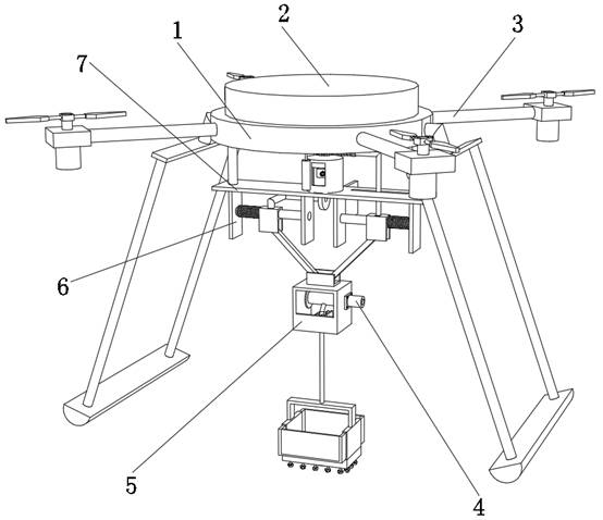
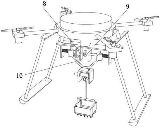
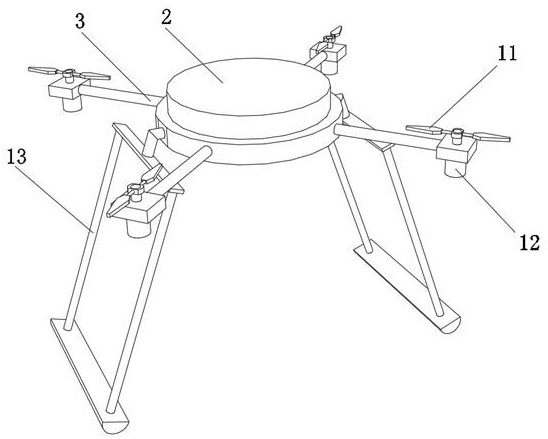
[0037] A fire-fighting drone with a load-bearing function, such as Figure 1-4As shown, it includes a support base 1 and a load-bearing assembly. The top outer wall of the support base 1 is fixed with a control box 2 by bolts. Two mounting brackets 6 are fixed, and the inner walls on both sides of the mounting bracket 6 are fixed with the same prismatic guide column 19 by bolts. The outer wall of the prismatic guide column 19 is slidably connected with a spring one 18, and the two ends of the spring one 18 are respectively clamped on the inner wall on one side of the mounting bracket 6 and the outer wall on one side of the sliding seat 17, and the inner walls of the two sliding seats 17 are both The connecting rod 10 is connected with the rotation of the rotating shaft, and the ends of the two connecting rods 10 away from the sliding seat 17 are connected with the same U-shaped frame 15 through the rotation of the rotating shaft, and the load-bearing assembly is fixed on the b...
Embodiment 2
[0045] A fire-fighting drone with a load-bearing function, such as Figure 7 As shown, in order to protect the loads in the sliding box 30; this embodiment makes the following additions on the basis of Embodiment 1: the outer wall of the bottom of the sliding box 30 is slidably connected with more than two lifting columns 35, two The outer wall at the bottom of the lifting column 35 is fixed with a semi-spherical buffer head 32 by screws, and the outer wall of the lifting column 35 is slidably connected with a spring 2 33, and the two ends of the spring 33 are respectively clamped on the inner wall and the The bottom inner wall of the sliding box 30; the whole sliding box 30 can be supported after the sliding box 30 falls on the ground by being provided with a hemispherical buffer head 32, and the sliding box 30 can be buffered by being provided with a spring 2 33 Function, so that the fragile objects can be effectively protected when conveying in the sliding box 30 .
[0046...
PUM
 Abstract
Description
Claims
Application Information