Cutting assembly of cutting pump

A technology of components and cutting blades, which is applied to pump elements, components of pumping devices for elastic fluids, pumps, etc., can solve the problems of small water inlet area, incomplete crushing of fibrous objects, and poor crushing effect of debris. , to achieve the effect of increasing the water inlet area, increasing the practical efficiency and preventing clogging

Pending Publication Date: 2021-07-13
JINING ANTAI MINING EQUIP MFG CO LTD
View PDF9 Cites 0 Cited by
  • Summary
  • Abstract
  • Description
  • Claims
  • Application Information

AI Technical Summary

Problems solved by technology

[0003] In order to solve the above technical problems, the present invention provides a cutting assembly of a cutting pump. The technical problems to be solved are: some objects are accumulated in the middle of the semi-open impeller, the water inlet area is small, the debris crushing effect is poor, and the fibrous objects are crushed Incomplete

Method used


Image

  • Cutting assembly of cutting pump
  • Cutting assembly of cutting pump
  • Cutting assembly of cutting pump

Examples


Embodiment 1

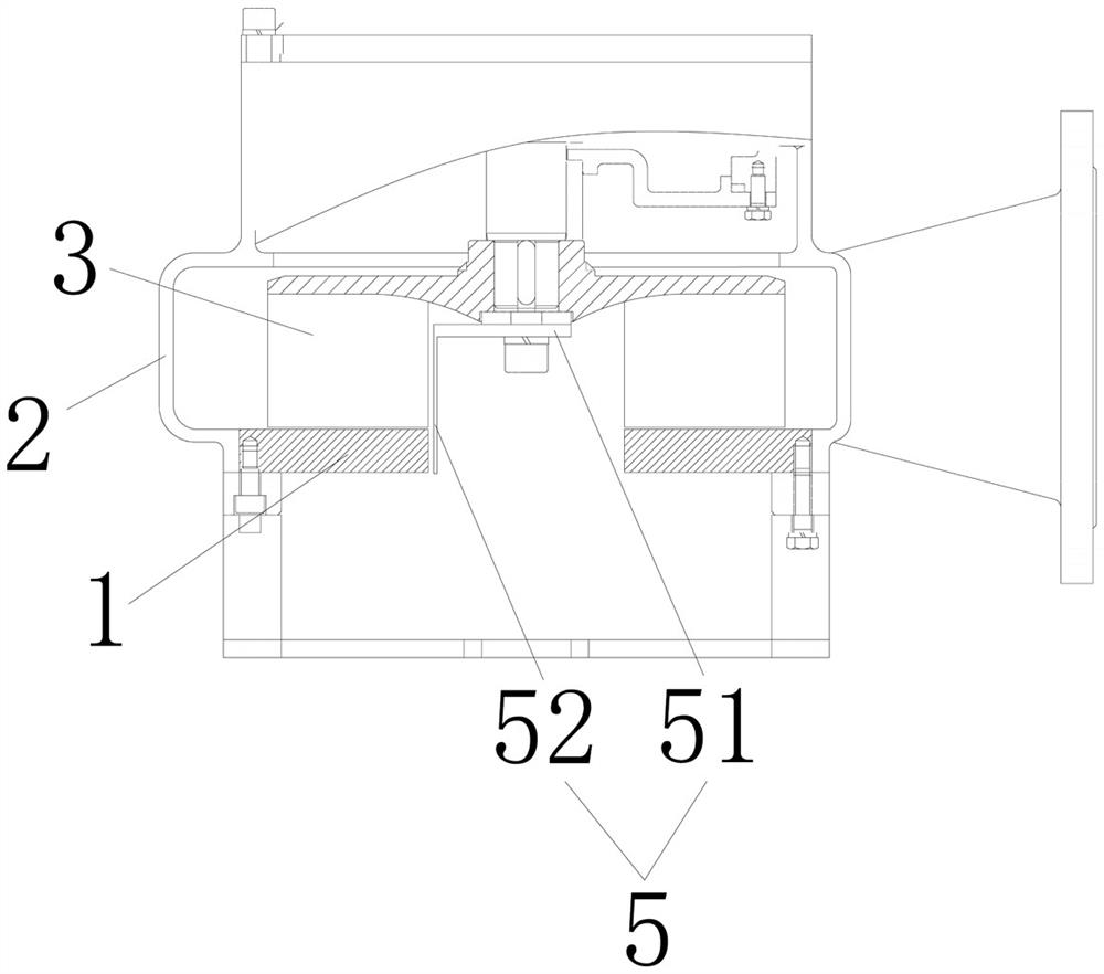
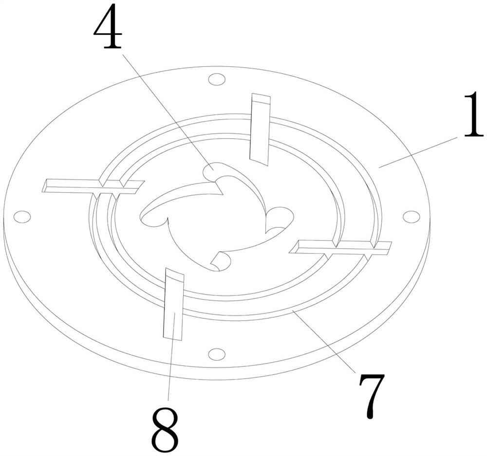
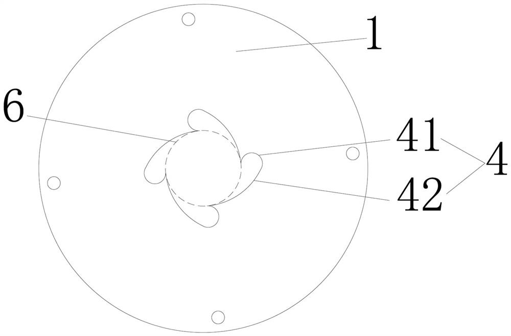
[0018] Embodiment 1: A cutting assembly of a cutting pump, including a pump cover 1, a volute 2 and a semi-open impeller 3, the pump cover 1 is arranged at the lower part of the volute 2, and the semi-open impeller 3 is arranged on the volute 2 in a rotational manner Inside, the semi-open impeller 3 has blades arranged along the circumference, and the pump cover 1 is provided with a water inlet channel, which is surrounded by a number of arc walls 4, compared with a simple round hole water inlet structure , increasing the water inlet area; the arc wall 4 is evenly arranged along the circumference 6 with the axis of the pump cover 1 as the center, and the cross section of the arc wall 4 includes a first arc segment 41 and a second arc segment 42, adjacent to the first The circular arc section 41 is connected end to end by the second circular arc section 42. This structure divides a single water inlet into a large water suction port and several vortex-shaped small water suction p...

Embodiment 2

[0023] Embodiment 2: On the basis of Embodiment 1, the water inlet channel is arranged as a spiral structure along its axial direction, and the spiral rotation direction is the same as that of the semi-open impeller 3. The first circular arc segment 41 and the second circular arc segment The arc section 42 deflects along the axis of the pump cover 1 and the deflection angle is γ, the range of γ is 0°<γ≤90°, the water flow through the water inlet channel is smoother, and it rotates like a vortex in each small water suction port; in this embodiment γ is set to 20°, and in other embodiments, γ can also be set to 5°, 30°, 40°, 50°, 60°, 70°, 80°, 90° or other angles; the first arc segment One end of 41 is circumscribed to the circumference 6, and the other end of the first arc segment 41 is inscribed to one end of the second arc segment 42. The tangent structure makes the water flow smoother and easier to form a vortex. The other end of the second arc segment 42 is in contact with ...


PUM


Abstract

The invention relates to the technical field of cutting pumps, in particular to a cutting assembly of a cutting pump. The cutting assembly comprises a pump cover, a volute and a semi-open impeller. The pump cover is arranged at the lower portion of the volute, the semi-open impeller is rotationally arranged in the volute, a water inlet channel is arranged on the pump cover, and the water inlet channel is enclosed by a plurality of arc walls. The arc walls are evenly arranged along the circumference with the axis of the pump cover as the circle center, the cross section of each arc wall comprises a first arc section and a second arc section, and the adjacent first arc sections are connected end to end through the second arc sections. The semi-open impeller is coaxially provided with a cutting knife, the cutting knife extends into the bottom of the water inlet channel, the water inlet area is increased, fibrous objects rotate and gather together in the arc walls and are rubbed into strips due to centrifugal force, and cutting of the semi-open impeller is facilitated. and the cutting knife is matched with the water inlet channel, so that blockage caused by accumulation of solid impurities in the middle of the semi-open impeller can be prevented, and the practical efficiency of the cutting pump is improved.

Description

Technical field: [0001] The invention relates to the technical field of cutting pumps, in particular to a cutting assembly of the cutting pump. Background technique: [0002] The cutting pump is a kind of sewage pump. There is a set of high-strength cutting impellers at the bottom to cooperate with the cutting disc, so that the cutting pump can chop up scum, plastic products and fibrous objects and discharge them smoothly under harsh conditions. The cutting assembly uses the semi-open impeller to suck debris into the volute through the water inlet. Due to the inertial force and centripetal force, some solids are accumulated in the middle of the semi-open impeller, and cannot be directly sucked into the semi-open impeller for cutting, resulting in Blockage; and some fibrous objects are not completely crushed, entangled on the impeller, and the cutting effect is poor. Invention content: [0003] In order to solve the above technical problems, the present invention provides ...

Claims


Application Information

Patent Timeline
Patent Type & Authority Applications(China)
IPC IPC(8): F04D7/04F04D29/00F04D29/42
CPCF04D7/045F04D29/007F04D29/426
Inventor 李志远张留柴春苗郝福合郭倩薛梅郭素英张宁宁周长帅郭怀波
Owner JINING ANTAI MINING EQUIP MFG CO LTD
Why Eureka
Try Eureka